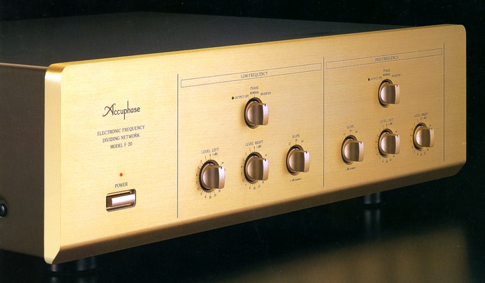
Accuphase F-20/F-20M
F-20
F-20M: ¥ 230,000 (released in May 1997)
: ¥ 260,000 (released in May 1997)
Commentary
A 2-way dedicated multi-channel divider that follows F-25 technology.
This model has 2 kinds of variations, F-20 and F-20M.
The F-20M was announced as a dedicated 2-way drive model of JBL's M9500 and Project K2S 9500 / S 7500. The F-20M is equipped with a dedicated filter amplifier circuit and a dedicated frequency board FB-650M, which provides the same filter characteristics as a speaker LC network.
The F-20M has the same appearance as the F-20, but the slope selector switch is fixed at -18dB/oct. It was also possible to convert the F-20 to the F-20M after purchase.
The F-20 has a two way configuration with a balanced input / output circuit with excellent transmission capability.
The balanced connection has the advantage of reducing noise interference, especially when a high-efficiency horn speaker is used, and enables high-purity signal transmission. Conventional unbalanced input / output is also handled by switching the switch on the rear panel.
We can expand it to 3 ways by adding another F-20.
The crossover frequencies can be changed by replacing the frequency board dedicated to each frequency. As a result, the shortest and straight signal path is realized, and the deterioration of sound quality is minimized. The devices that have a significant impact on sound quality are carefully selected, mainly PPS capacitors and precision carbon film resistors, to minimize the deterioration of sound quality and colorization.
The frequency board is installed and removed in a slot on the rear panel side. The frequency board is common with the F-25 and is sold separately.
The filter curve used to divide the frequency uses Gaussian characteristics.
This type of filter is also used in high-performance measuring instruments such as spectrum analyzers. Compared with conventional Butterworth characteristics, it has higher impulse reproducibility and enables more faithful reproduction of the original waveform.
A GIC type filter circuit is used to create the cutoff characteristics.
This filter is a circuit that uses only CR to implement a filter that could only be assembled with LC in the past. Compared with conventional feedback filter circuits, this filter does not pass through the amplifier in the passband, so the purity of the signal is maintained.
You can also select a constant to keep the frequency and attenuation of the filter accurate.
The attenuation characteristics of the filter can be selected with the switch on the front side, and the slope can be selected from three types : -12dB/oct, -18dB/oct, and -24dB/oct. This switch is independent of Low and High, and you can set the slope for each band separately.
A modular output balance circuit is adopted.
The output balance circuit consists of two pairs of amplifiers, each of which is fed back to the other. By using a slotted structure, it is possible to send out positive and negative symmetrical signals with low impedance. In addition, since this circuit is a circuit type in which positive and negative symmetrical signals are floated from the ground, even if one side of the output is grounded, both amplifiers will operate and the output voltage will not change. This allows only one output to be connected to the ground line for normal unbalanced connections, so that there is no change in sound quality between balanced and unbalanced connections.
In order to realize this circuit with more stable operation, the main circuits are modularized on a alumina ceramics substrate with excellent heat conduction.
A phase switch is mounted on each Low/High channel to invert the phase of the output.
There is no need to worry about the loss of sound quality because the switching method is only to exchange the connection of the balance output amplifier.
A selector switch is mounted on the LOW output section of the rear panel in order to support the sub-woofer system in which the left and right signals of the low frequency range with broad directivity are mixed and output from one large woofer.
The output control is equipped with an attenuator, which can be adjusted by 0.5 dB steps from 0 to -8dB, by 1 dB steps from -8dB to -20dB, and by - ∞. Since this attenuator is equipped independently on the left and right sides, the level of each band can be adjusted precisely and finely.
.jpg)
.jpg)
.jpg)
.jpg)
.jpg)
.jpg)
.jpg)
.jpg)
.jpg)
Model Rating
| Type | Channel divider | ||||||||||||||||||||||||||||||||||||||||||||
| Maximum Input Level (Distortion Factor 0.01% or less, 20 Hz to 20 kHz) | Balanced:5.0V Unbalanced:5.0V |
||||||||||||||||||||||||||||||||||||||||||||
| Total Harmonic Distortion Factor (20 Hz to 20 kHz, 2.0 V output) | 0.003% | ||||||||||||||||||||||||||||||||||||||||||||
| Frequency Response (Single Channel Equivalent Band) | 20 Hz ~ 20 kHz + 0 -0.2 dB 0.5 Hz ~ 300 kHz + 0 -3.0 dB |
||||||||||||||||||||||||||||||||||||||||||||
| Gain | 0dB | ||||||||||||||||||||||||||||||||||||||||||||
| Crossover frequency | Change by replacement of crossover board Standard frequency : 21 points |
||||||||||||||||||||||||||||||||||||||||||||
| Crossover characteristic | -3.0 dB + / - 5% | ||||||||||||||||||||||||||||||||||||||||||||
| Slope characteristic | -12dB/oct., -18dB/oct., -24dB/oct. Switch-over type |
||||||||||||||||||||||||||||||||||||||||||||
| Input impedance | Balanced : 40k Ω Unbalanced : 20k Ω |
||||||||||||||||||||||||||||||||||||||||||||
| Output impedance | Balanced : 50 Ω Unbalanced : 50 Ω |
||||||||||||||||||||||||||||||||||||||||||||
| S/N (output 0.5 v, IHF-A corrected) | 100dB | ||||||||||||||||||||||||||||||||||||||||||||
| Minimum load impedance | Balanced : 600 Ω Unbalanced : 600 Ω |
||||||||||||||||||||||||||||||||||||||||||||
| Level adjustment | 0 to -8dB, 0.5 dB step -8dB to -20dB, 1 dB step - ∞ |
||||||||||||||||||||||||||||||||||||||||||||
| Power supply voltage | 100 VAC, 50Hz/60Hz | ||||||||||||||||||||||||||||||||||||||||||||
| Power consumption | 20W | ||||||||||||||||||||||||||||||||||||||||||||
| Maximum external dimensions | Width 475x Height 150x Depth 395 mm | ||||||||||||||||||||||||||||||||||||||||||||
| Weight | 10.4kg | ||||||||||||||||||||||||||||||||||||||||||||
| Remarks | Remodeling of F-20 to F-20M (¥ 10,000) FB-650M(¥30,000) |
||||||||||||||||||||||||||||||||||||||||||||
| Sold Separately | Frequency board (¥ 15,000 each)
|