Accuphase F-15
¥ 200,000 (released in August 1981)
Commentary
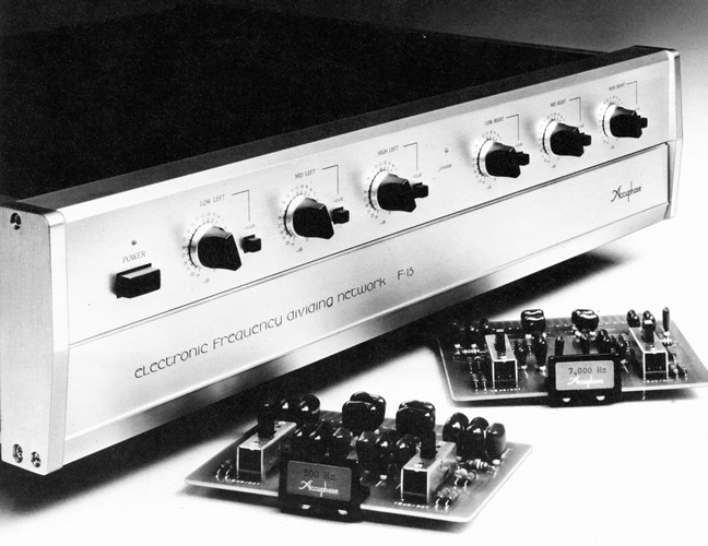
Channel divider with interchangeable crossover board.
The F-15 consists of a combination of an active filter and a buffer amplifier. All unit amplifiers have the same configuration with a gain of 1. The active filter amplifier that creates crossover characteristics is combined with a CR element to create the characteristics.
A push-pull circuit is used for the unit amplifier. The input is a source follower of low noise and high gmFET complimentary service, and the complimentary service is a push-pull circuit with wide-band transistors.
This circuit has no loop feedback, and excellent performance is obtained by the push-pull system and local period system as well as the careful selection of elements.
The DC servo system is used for the output unit amplifier in order to prevent the generation of DC component and to stabilize it.
Since the gain of the unit amplifier is 1, if the servo time constant is set at one point, the time constant becomes larger and the lowering characteristic of the low-frequency range becomes broader and the distortion increases. To solve this problem, the F-15 uses a series connection of the mirror integration circuit and sets the time constant in 3-stage configuration to reduce the CR per stage and improve the low-frequency distortion characteristics.
The front panel is equipped with low, mid and high level control with independent left and right channels.
The attenuator is a precision 1 dB step type, but it can be controlled in 0.5 dB steps by a combination of 0.5 dB shift switches. The adjustment range is 41 points of 0 to -20.5 dB and - ∞.
You can change the crossover frequency by changing the crossover board for each frequency.
Each crossover board is equipped with left and right channel CR elements. These elements, which have a significant effect on sound quality, are mainly composed of precision metal film resistors and high-quality silbird mica capacitors to minimize degradation and colorization of sound quality.
The crossover board opens the sub-panel at the bottom of the front panel and inserts it into a socket.
Two types of cutoff attenuation slope characteristics can be selected : -12dB/oct. and -18dB/oct.
This can be done with the changeover switch on the crossover board.
A protective circuit is mounted to prevent damage to the speakers due to shock noise when the crossover board is replaced in the operating state. In this protective circuit, the muting is activated just before the board is removed from the socket electrode and the output is cut off.
For 2-way use, insert a 2-way board (sold separately) into the middle and high area board socket.
When using it as 4-5-way, add another F-15.
There was a special rosewood cabinet sold separately.
.jpg)
.jpg)
.jpg)
.jpg)
.jpg)
Model Rating
| Type | Channel divider | |||||||||||||||||||||||||||||||||||||||||||||||||||||||||||||||||||||
| Maximum Input Level (Distortion Factor 0.01% or less, 20 Hz to 20 kHz) | Balanced : 7.0 v, XLR type Unbalanced : 7.0 v, RCA |
|||||||||||||||||||||||||||||||||||||||||||||||||||||||||||||||||||||
| Total Harmonic Distortion Factor (20 Hz to 20 kHz, 2.0 V output) | 0.003% | |||||||||||||||||||||||||||||||||||||||||||||||||||||||||||||||||||||
| Frequency Response (Single Channel Equivalent Band) | 20 Hz ~ 20 kHz + 0 -0.2 dB 0.5 Hz ~ 300 kHz + 0 -3.0 dB |
|||||||||||||||||||||||||||||||||||||||||||||||||||||||||||||||||||||
| Gain | 0dB | |||||||||||||||||||||||||||||||||||||||||||||||||||||||||||||||||||||
| Crossover frequency | Change by replacement of crossover board Standard frequency : 21 points |
|||||||||||||||||||||||||||||||||||||||||||||||||||||||||||||||||||||
| Crossover characteristic | -3.0 dB + / - 5% | |||||||||||||||||||||||||||||||||||||||||||||||||||||||||||||||||||||
| Slope characteristic | -12dB/oct., -18dB/oct., -24dB/oct. Switch-over type |
|||||||||||||||||||||||||||||||||||||||||||||||||||||||||||||||||||||
| Input impedance | Balanced : 40k Ω (20k Ω / 20k Ω) Unbalanced : 20k Ω |
|||||||||||||||||||||||||||||||||||||||||||||||||||||||||||||||||||||
| Output impedance | Balanced : 50 Ω (25 Ω / 25 Ω) Unbalanced : 50 Ω |
|||||||||||||||||||||||||||||||||||||||||||||||||||||||||||||||||||||
| S/N (output 0.5 v, IHF-A corrected) | 100dB | |||||||||||||||||||||||||||||||||||||||||||||||||||||||||||||||||||||
| Minimum load impedance | Balanced : 600 Ω Unbalanced : 600 Ω |
|||||||||||||||||||||||||||||||||||||||||||||||||||||||||||||||||||||
| Level adjustment | 0 dB to -20.5 dB, 1 dB step and ∞ Each band is left and right independent |
|||||||||||||||||||||||||||||||||||||||||||||||||||||||||||||||||||||
| Power supply voltage | AC100V/117V/220V/240V, 50Hz/60Hz | |||||||||||||||||||||||||||||||||||||||||||||||||||||||||||||||||||||
| Power consumption | 32W | |||||||||||||||||||||||||||||||||||||||||||||||||||||||||||||||||||||
| Maximum external dimensions | Width 475x Height 170x Depth 380 mm | |||||||||||||||||||||||||||||||||||||||||||||||||||||||||||||||||||||
| Weight | 16.0kg | |||||||||||||||||||||||||||||||||||||||||||||||||||||||||||||||||||||
| Sold Separately | Wood Cabinet A-12 (¥ 16,000) Frequency board
|
.jpg) |
.jpg) |
Since 2-way has a single crossover frequency, set a board with that frequency for LOW/MID, and use a 2-way board (which jumps the circuit inside) for MID/HIGH. |
In the case of 3 way, it is the most standard usage. |
.jpg) |
.jpg) |
In case of 4-way, 2 F-15s are used. |
For 5-way, two F-15s are connected in series. |