Accuphase P-360
¥ 370,000 (released in March 1991)
Commentary
This stereo power amplifier was developed as a successor to the P-300 series.
The design has been changed to the symmetric design used in the series of accu-phase power amplifiers, and the basic functions and other features are the same as those of the 300 series.
The large current capacity transistor is composed of 7-parallel push-pull, and a current of 210A is obtained in 1 ms.
A high-efficiency large 1 kva toroidal transformer is used for the transformer of the power supply section, and 40,000 μ F/80Vx2 is used for the smoothing capacitor. Flat output voltage is obtained from 20 hz to 20000 hz.
AccuPhase's original MOS FET + cascode push-pull circuit is used for the drive stage to improve the characteristics at the time of small signal.
In addition, the output stage is a bipolar transistor with a positive temperature gradient, and the drive stage is a MOS FET with a negative temperature gradient. By offsetting each other, a good and stable power amplifier is formed.
The predriver also uses a class A cascode push-pull circuit to increase the stability of the MOS FET.
The amplifier input uses a direct connection system in which the signal is directly applied.
Even a small amount of DC input can produce a large output and cause damage to the speakers. Therefore, the DC servo is applied to prevent amplification in the DC area and DC is cut off.
In this method, NFB is applied so as to suppress the output offset of the amplifier itself at the same time, so stable operation against temperature change is realized.
The input stage is a balanced differential pure complimentary service push-pull type, and a high-impedance / low-impedance FET input buffer amplifier is connected to the + (non-inverted) and - (inverted) inputs, respectively.
When a balanced input is used, it is directly input to these jacks for high-purity amplification.
When a bridge connection is made, the same signal is input to the + input of one amplifier and the - input of the other amplifier simultaneously.
In this way, no extra circuit such as a converter is added for all types of input, and homogeneous amplification is possible.
In addition to the normal 20k Ω RCA pin jack input, there is also a 40k Ω balance input. The international standard XLR-type connector allows the balance output of any impedance to be connected.
Since the balance input circuit is designed to inject the signal directly into the positive and negative inputs of the differential input circuit, it is necessary to insert a level control into each of the positive and negative inputs. Therefore, the P-360 uses a 1-dB step-by-step double-attenuator with less interlocking error. The input circuit is designed so that the frequency characteristics do not change at the position of the level control.
The bridge connection of the P-360 provides twice the output of the 4 Ω load in stereo operation.
In normal bridge connection, a phase inversion circuit is inserted into one amplifier. The P-360 uses the polarity of the differential input circuit of the two amplifiers to change the connection so that the signals are input opposite to each other. This is a pure switching circuit without inserting any special circuit.
The input level regulator uses a mirror-finished resistor with a particularly low distortion factor.
By mirror finishing, it has good strain characteristics and excellent wear resistance, and there is no grease or other material that impairs sound quality between brush resistors.
In addition, in general VR, the lead wire is sent out to the outside through the caulking part by the resistor, and the brush becomes the slider (rotor), but in P-360, the resistor becomes the rotor, and the brush part is fixed and comes out directly to the outside.
As a result, the number of metal joints has been reduced from five to three, reducing the adverse effect on sound quality.
The input circuit is - (inverted) and + (non-inverted), and consists of two circuits per channel. It is a 1-dB-step attenuator type with less interlocking error, and the input level can be controlled accurately.
A special amplifier for headphones is provided for high-quality sound reproduction by headphones.
The input stage uses an FET servocontrol amplifier, so it does not affect the main circuit.
You can control the volume of your headphones regardless of the volume of your speakers.
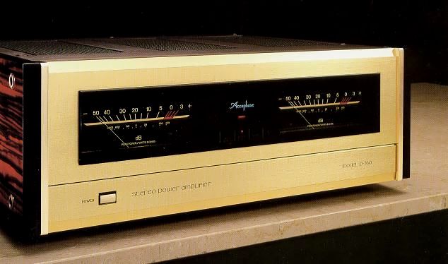
The output meter has a logarithmic compression of the output meter, the level reproduction between -50dB and + 3 dB can be seen at a glance. The output voltage at dB and 8 Ω load can be directly read.
It is also equipped with a switch that turns off the meter and lights.
The input is one balanced system and two unbalanced systems, which can be switched by the switch in the front panel.
Unbalanced line 1 is installed in the front sub-panel.
You can switch between two types of speaker output jacks.
It can also be driven by parallel connection with a changeover switch.
With a simple design and champagne gold finish, everything except the power switch is stored inside the lower sub panel.
Both sides have a natural Persimmon finish board.
.JPG)
.JPG)
.JPG)
.JPG)
.JPG)
.JPG)
.JPG)
Model Rating
| Type | Stereo power amplifier |
| Continuous average power (20 Hz to 20 kHz) |
Stereo type (both channels operate simultaneously) 400W/ch : 2 Ω load 300W/ch : 4 Ω load 200W/ch : 8 Ω load 100W/ch : 16 Ω load Monophonic Specification (Bridge Connection) 800W : 4 Ω load 600W : 8 Ω load 400W : 16 Ω load |
| Harmonic distortion factor | Stereo type (both channels operate simultaneously) 0.02%, 2 Ω ~ 16 Ω load Monophonic Specification (Bridge Connection) 0.02%, 4 Ω ~ 16 Ω load |
| IM distortion factor | 0.003% |
| Frequency characteristic | 20 Hz ~ 20 kHz + 0 -0.2 dB (Continuous Average Output, Level Control MAX) 0.5 Hz ~ 16k0Hz + 0 -3.0 dB (at 1W output, level control MAX ~ -6dB) |
| Gain | 28.0 dB (for stereo / monophonic specifications) |
| Load impedance | Stereo specification : 2 Ω ~ 16 Ω Monophonic Specification (Bridge Connection) : 4 Ω ~ 16 Ω |
| Damping factor | Stereo specification : 300 Monophonic specification (bridge connection) : 150 |
| Input sensitivity (8 Ω load) | Stereo specification 1.59 V : continuous average output 0.11 V : 1W output Monophonic Specification (Bridge Connection) 2.76 V : continuous average output 0.11 V : 1W output |
| Input impedance | Balance : 40k Ω Unbalanced : 20k Ω |
| S/N (A correction) | 120 dB (Input Short, Continuous Average Output) 100 dB (Input 1k Ω, 1W output) |
| Stereo headphone | Applicable Impedance : 4 Ω ~ 1000 Ω |
| Output meter | Logarithmic compression type, -50dB to + 3 dB and output direct-reading scale |
| Semiconductor used | Transistor : 63 FET : 32 IC : 10 Diode : 77 pcs |
| Pwer | 100 V, 117 V, 220 V, 240 V, 50Hz/60Hz |
| Power consumption | No input : 100W Electrical Appliance and Material Control Law : 590W 8 Ω rated output : 633W |
| External dimensions | Width 475x Height 180 (Including Legs) x Depth 409 mm |
| Weight | 27.4kg |