Accuphase P-11
¥ 230,000 (released in July 1989)
Commentary
In addition to basic performance such as frequency characteristics, distortion factor, and S/N, a stereo power amplifier with improved low-impedance driving capability to send sufficient energy to speakers with complex characteristics.
The output stage consists of three parallel push-pull large output transistors with a Pc (collector loss) of 130W, which provides stable output even at low impedance.
The drive stage uses an original power MOS FET only for Accu-phase as a power element with excellent characteristics of withstanding high voltage.
The voltage amplification of the preceding stage is carried out by the differential amplifier stage, and a buffer stage is provided to prevent interference with the preamp connected before this stage and the input level control.
This buffer stage adopts a cascode method using FET, and has excellent high-frequency characteristics and stable operation even in a large change of input impedance.
The power supply section uses a large toroidal transformer with excellent fluctuation coefficient to provide sufficient margin even at maximum output.
In order to prevent interference at each stage, separate windings of the transformer are supplied to the output stage and the front stage, respectively. In addition, the front stage is composed of independent left and right rectifiers and filters, so that interference at the front and rear stages and left and right channels is minimized.
The input signal is directly input using a direct connection system.
When a preamp with large DC drift is connected, the DC servo system is adopted to prevent it from being amplified and appearing on the output and damaging the speaker. In addition to cutting off DC, the DC drift of the amplifier itself due to temperature change is stabilized.
It can also be used as a monaural power amplifier with a bridge connection for more powerful output.
Bridge connection is equivalent to push-pull driving of two amplifiers by a method in which signals of the same magnitude and phase difference of 180 ゜ (opposite phase) are input to the same amplifier, and the output power of sy is taken out from the output terminals of both amplifiers to obtain twice the output power of 4 ohm load when stereo driving is performed at 8 ohm load.
Normally, when a bridge is connected, a phase inversion circuit is inserted into one amplifier. However, the P-11 uses the polarity of the differential input circuit of two amplifiers to create an ideal switching circuit without inserting any amplifier.
In addition to the normal phono jack input, there is a full-scale balance input.
The balance input circuit of the P-11 has an ideal configuration in which the signal is input directly to the positive and negative inputs of the differential input circuit.
For the level control that must be inserted into both the plus and minus positions, we have adopted a 1 db step double attenuator with less interlocking error.
Two outputs are provided so that two pairs of speakers can be driven.
Each is controlled by an independent high-current relay, and with A + B, two systems are connected in parallel so that a bi-wired speaker can be connected.
Equipped with an overload indicator to indicate the maximum output level.
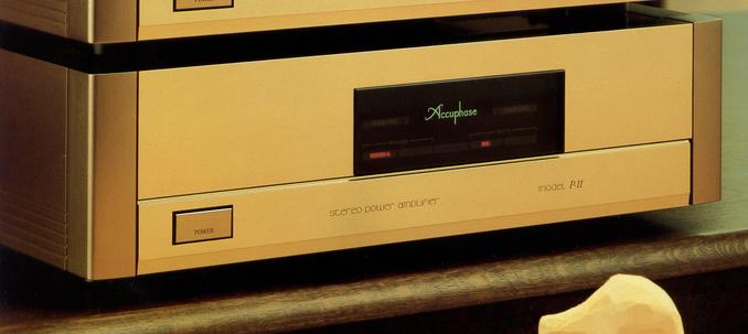
Based on the champagne gold scratch hairline finish panel which is the basis of Accuphase, it is designed with thick glass display in the center and treated with thick metal end block on both sides.
.JPG)
.JPG)
.JPG)
Model Rating
| Type | Stereo power amplifier | ||||
| Continuous average power (20 Hz to 20 kHz) |
|
||||
| Total harmonic distortion factor |
|
||||
| IM distortion factor | 0.003% | ||||
| Frequency characteristic | 20 Hz ~ 20 kHz + 0 -0.2 dB (at continuous average output, level control maximum) 0.5 Hz ~ 160 kHz + 0 -3.0 dB (Level Control Maximum ~ -6dB at 1W Output) |
||||
| Gain | 28.0 dB (both stereo and monaural specifications) | ||||
| Load impedance | Stereo specification : 4 Ω ~ 16 Ω Monaural specification (bridge connection) : 8 Ω ~ 16 Ω |
||||
| Damping factor | Stereo specification : 200 Monaural specification (bridge connection) : 100 |
||||
| Input Sensitivity (8 Ω) |
|
||||
| Input impedance | Balance : 40k Ω Unbalanced : 20k Ω |
||||
| S/N (A correction) | 115 dB (Input Short, Continuous Average Output) 93 db (at 1k Ω input, 1W output) |
||||
| Stereo headphone | Applicable Impedance : 4 Ω ~ 100 Ω | ||||
| Semiconductor used | Transistor : 41 FET : 14 IC : 4 Diode : 60 |
||||
| Power supply voltage | AC100V/117V/220V/240V, 50Hz/60Hz | ||||
| Power consumption | No input : 45W Electrical Appliance and Material Control Law : 300W 8 Ω rated output : 480W |
||||
| External dimensions | Width 445x Height 131 (Including Legs) x Depth 388 mm | ||||
| Weight | 18.1kg |