Accuphase M-100
¥ 500,000 (1 unit, released in July 1981)
Commentary
A monaural power amplifier developed in pursuit of the ideal power amplifier with emphasis on "low open-loop output impedance" and "high current supply power supply and output stage" for ideal speaker drive.
The output stage consists of 12 parallel push-pull wide-band bipolar transistors with Pc (collector loss) of 200W (total 24 output transistors) for a total power capacity of 4.8 kW with sufficient margin.
The output transistors are divided into two groups and attached to the left and right large heat sinks to improve the heat dissipation effect. Since both heat sinks are not thermally coupled, the tendency is accelerated when there is a thermal imbalance, and only one of them will overheat and lead to the destruction of the element. In order to prevent such thermal imbalance, a bias balance circuit is adopted. In this circuit, the element connected to the base of the output element is attached to the other heat sink, the temperature is detected, and the bias current is controlled. By making the temperature almost equal to each other, stable operation is achieved.
The drive stage is composed of MOS FET for power amplification which is an original of AccuPhase. It performs low-impedance high-current drive and significantly improves high-frequency characteristics.
In addition, since the thermal characteristics act in the direction to stabilize the bipolar transistor, the bias current of the output stage is stabilized. Therefore, the emitter resistance of the output stage can be lowered. Moreover, the equivalent emitter resistance of 1/12 is lowered by 12 parallel, and the switching distortion caused by the cutoff of the bias of the output transistor is almost eliminated.
The pre-drive stage is composed of cascode-connected push-pull, and achieves both excellent high-frequency characteristics without mirror effect and large amplitude operation.
In addition, a relatively large bias current is applied to 24 output elements, and a pure class A operation region is achieved up to an output of 5W.
The circuit consists of a conventional Accu-phase full amplification stage push-pull, which improves open-loop characteristics to the limit.
The input is received by a dual FET, and a cascode bootstrap differential push-pull configuration is adopted. The cascode bootstrap provides a large gain, improves the high-frequency characteristics, and prevents the increase of distortion due to the increase of input impedance (change of input level control).
The dual-FET push-pull input circuit does not generate DC at the input, so the input capacitor can be removed. However, in this condition, DC is generated at the output when a preamp with a large DC leakage is connected, which adversely affects the speaker.
The M-100 uses a DC servo amplifier to apply DC feedback to shut off DC, and also suppresses DC drift generated in the circuit.
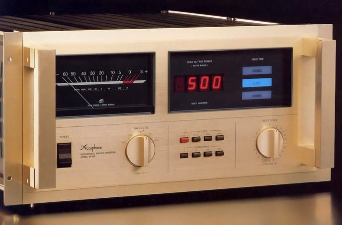
This is the world's first power amplifier equipped with a digital peak power direct reader.
In this circuit, the output signal of the amplifier is converted to an easy-to-read magnification by a range selector switch (attenuator) and input to a peak detector. Here, the + and - waveforms are all aligned to the + side. In the next step, the peak value of the signal is held. The peak value is sent to a 12-bit A/D converter to convert it into a digital signal. The digital signal is input to a 4-bit microprocessor, which converts voltage to power, selects peaks within a certain period of time and displays them on the LED.
The microprocessor also outputs a reset signal for setting the hold time and starting a new hold, a range switching signal and a signal indicating that the display range has been exceeded.
There are four range switches, x1, x0. 1, x0. 01, and x0. 001. With these switches, the range between 0.001W and 999W can be read directly by three digits.
There are three types of hold time : 0.5 second, 3 second and 30 minute. If you use a 30 minute range, you can read the peak value of one side of the record. You can know the maximum cutting level by comparing it with the reference signal of the test record.
In addition to the digital display, it is equipped with an external magnetic type precision large meter that can monitor output by dB and watt value.
The logarithmic compression type can read up to -60dB (0 dB = 500W, -60dB = 0.0005W).
Equipped with a 25-contact rotary switch for communication equipment and a full-scale step-type attenuator using high-precision metal-coated resistor.
A 1-dB step between 0 and -20dB, followed by -23dB, -26dB, -30dB and - ∞ with an accuracy of ± 0.1 dB.
Equipped with a low filter that cuts out unwanted low-frequency noise.
Four types of cutoff frequencies can be selected : 10 Hz and 17 Hz for subsonic range, 30 Hz and 50 Hz for commercial use, and slope characteristics are -12dB/oct.
For these switching, a relay dedicated to each frequency is installed in the circuit board, and this relay is controlled by a switch on the front panel.
It is equipped with a phase switch that inverts the phase of the output signal with respect to the input signal so that the phases of the channels can be adjusted.
In addition, two M-100 units per channel can be used for bridge connection to increase the power to 8 Ω load 1.6 kw.
When multiple M-100s are used, the hold start timing of the digital display will be out of sync.
In addition to the digital display, the timing of the relay of the output circuit when the power is ON / OFF can also be adjusted by mounting the sync signal terminal to synchronize and start simultaneously.
A 1.5 meter cable with connectors is included, and a 5 meter cable is sold separately.
In addition to the normal phono jack, the input terminal is also equipped with a business canon-type connector.
A heat dissipation fan is sold separately. It is ideal for installation in a place where heat dissipation effect is poor or for long-term high power operation.
The fan can be mounted on the rear panel.
Persimmon panel with 24 mm thick wood finish is sold separately.
.JPG)
.JPG)
.JPG)
.JPG)
.JPG)
Model Rating
| Type | Monaural power amplifier | ||||||||||||||
| Continuous average power (20 Hz to 20 kHz, Distortion Factor 0.01%) |
1000W (2 Ω) 800W (4 Ω) 500W (8 Ω) 250W (16 Ω) |
||||||||||||||
| Total harmonic distortion factor | 0.01% (2 Ω ~ 16 Ω, 0.25W ~ Continuous Average Output Between, 20 Hz ~ 20 kHz) | ||||||||||||||
| IM Distortion Factor (EIA) | 0.003% | ||||||||||||||
| Frequency characteristic | 20 Hz ~ 20 kHz ± 0 dB (Continuous Average Output, Level Control MAX) 0.5 Hz ~ 400 kHz + 0 -3dB (at 1W Output, Level Control MAX) 0.5 Hz ~ 140 kHz + 0 -3dB (EIA, at 1W output, level control -6dB) |
||||||||||||||
| Gain | 28dB | ||||||||||||||
| Load impedance | 2 Ω ~ 16 Ω | ||||||||||||||
| Damping factor (EIA) | 300 (50 Hz, 8 Ω) | ||||||||||||||
| Input Sensitivity / Impedance | 2.6V/20k Ω (at continuous average output) 0.12V/20k Ω (at EIA, 1W output) |
||||||||||||||
| Input level adjustment | Step-type attenuator Attenuation : 25 contacts of 1 dB step between 0 and -20dB, -23dB, -30dB, - ∞ Error : within ± 0.1 dB |
||||||||||||||
| S/N (A correction) | 130 dB (input short at continuous average output) 100 dB (EIA, 1W output, input 1k Ω) |
||||||||||||||
| Low filter | 10Hz/17Hz/30Hz/50Hz, -12dB/oct. | ||||||||||||||
| Output meter | Logarithmic compression peak indication type, -60dB to + 3 dB and output direct reading scale | ||||||||||||||
| Digital power display |
|
||||||||||||||
| Semiconductor used | Transistor : 57 FET : 5 pcs IC : 21 Diode : 65 pcs |
||||||||||||||
| Power supply voltage | AC100V/117V/220V/240V, 50Hz/60Hz | ||||||||||||||
| Power consumption | 175W (no input) 490W (Electrical Appliance and Material Control Law) 780W (at 8 Ω load 500W output) |
||||||||||||||
| External dimensions | Width 480x Height 232 (Including Legs) x Depth 476 mm | ||||||||||||||
| Weight | 41.5kg | ||||||||||||||
| Attachment | Timing Cable (1.5m) | ||||||||||||||
| Sold Separately | Sidewood A-14 (set with mounting bracket, ¥ 16,000) Heat Dissipation Fan O-81 (set, ¥ 8,000) Timing Cable TC-11 (10m, ¥ 3,000) |