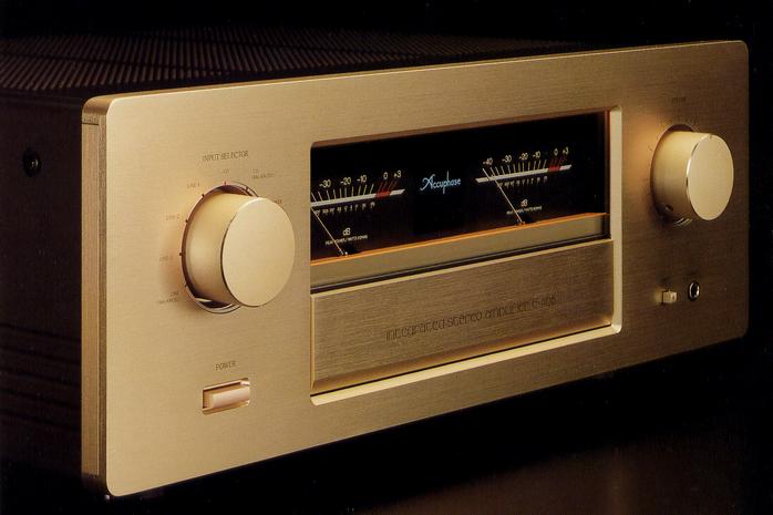
Accuphase E-406
¥ 380,000 (released in June 1993)
Commentary
A pre-main amplifier developed by ACPHASE as the ideal form of an integrated amplifier by combining the development technology cultivated for many years in the separate amplifier group and making the preamplifier part and power amplifier part completely independent.
The output stage of the power amplifier consists of four parallel output elements, which are attached to a large heat sink to achieve stable operation even under low impedance loads.
In order to prevent output offset voltage (a phenomenon in which DC component leaks to the output), AccuPhase's original DC servo amplifier is used for NFB (feedback circuit), so that no DC component is generated in the speaker output, and stable operation is obtained even in power supply fluctuation and temperature change.
The input circuit is composed of an Accu-phase original differential complimentary service push-pull circuit to realize high CMRR (in-phase component rejection ratio).
This differential is a Darlington-connected, emitter-grounded push-pull amplifier. The signal is guided to the driver section of the output stage. This symmetrical push-pull configuration enables highly stable operation.
The power supply section uses independent power amplifier / preamp section transformers, and each power supply uses a dedicated power supply to completely prevent mutual interference between amplifiers.
The power transformer used for the power amplifier is of a weight class up to 9 kg, and a large-capacity capacitor of 33,000 μ Fx2 is used for smoothing.
The speaker terminal uses a large speaker terminal made of solid brass that can be used with very thick cables. This terminal can also be used with banana plugs.
In addition, by selecting the A + B position, a by-wire connection is also available.
Equipped with a large power meter that can monitor output power.
Since this meter is logarithmic compression type, it is possible to see a wide dynamic range at one time. Moreover, it is possible to accurately monitor changing music signals by capturing peaks.
The line amplifier section consists of discrete parts. The basic configuration is an original Accu-Phase, differential-pure complimentary service push-pull. The output stage is equipped with a single-ended push-pull emitter-follower for a simple configuration, which reduces the phase correction of each stage and provides more natural sound quality.
A local active ripple filter power supply is used to compensate for crosstalk from the main power supply.
The equalizer amplifier section is equipped with a dedicated input circuit that takes into account the characteristics of each MC type and MM type cartridge.
In consideration of the high output voltage and impedance at the MM input, it is composed of FET elements that can maintain high input impedance over the whole round fractional band. In addition, in order to receive small signals with low impedance at the MC input, a differential input circuit is composed of low-noise elements to make the impedance of the NFB loop low, enabling low-noise reproduction.
In order to increase the purity of circuit connections and improve sound quality, a gold plate is used for the printed circuit board of the main signal path.
High-purity copper is used for the printed circuit board, and by forming a gold plate on it, the influence of the skin effect is reduced and good conductivity is obtained.
In order to configure the shortest and straight signal path, relays are installed where switching is necessary, and logic relay control is used to electronically control these relays.
The relay used for this purpose is a nitrogen gas-filled sealed relay for the communication industry. The contact of this relay is a gold-plated cross-bar twin type with low contact resistance and high durability.
The tone control section is equipped with an add-on active filter tone control that is used in full-scale graphic equalizers.
This method is superior to conventional tone control in terms of sound quality. In this method, an original flat signal passes straight through, another characteristic is created as necessary, and the signal is added or subtracted from the flat signal.
Comes with a remote commander that can switch input and adjust volume.
Since the input selector switches relays electronically, this logic circuit is controlled by the commander so that there is no deterioration in sound quality.
In addition, the input level regulator is equipped with a rotating resistor with a low distortion factor, a gear mechanism and an electric motor for remote control. The motor is covered with a magnetic shield made of silicon steel to reduce noise.
The switching timing is controlled on the order of milliseconds (ms) using a micro computer, so there is no switching noise.
Equipped with a balanced input.
In balanced transmission, positive and negative signals are simultaneously transmitted at the same voltage on the transmitting side and inverted 180 ° in phase on the receiving side. These signals are received by a + amplifier and a - amplifier on the receiving side, and they are accurately synthesized. In this case, noise components generated in the cable enter both poles in phase, so when they are synthesized, they are cancelled, only the noise components disappear, and the purity of the music signal increases.
A special amplifier for headphones is installed to give consideration to sound quality.
The preamp section and power amplifier section are separated, and a changeover switch for use as an independent amplifier and its input / output terminals are mounted.
.JPG)
.JPG)
.JPG)
.JPG)
.JPG)
.JPG)
.JPG)
.JPG)
.JPG)
.JPG)
Model Rating
| Type | Integrated stereo amplifier | |||||||||||||||||||||||||
| Continuous average output (both channel operation 20 Hz to 20 kHz, Distortion Factor 0.02%) |
250W/ch (4 Ω) 170W/ch (8 Ω) |
|||||||||||||||||||||||||
| Total harmonic distortion factor (both channel operation) | 0.02% (4 Ω to 16 Ω load, 0.25W to continuous output, 20 Hz to 20 kHz) | |||||||||||||||||||||||||
| IM distortion factor | 0.01% | |||||||||||||||||||||||||
| Frequency characteristic |
|
|||||||||||||||||||||||||
| Damping factor | 120 (8 Ω load, 50 Hz) | |||||||||||||||||||||||||
| Input Sensitivity / Impedance (Rated Output / EIA1W Output) |
AD input (MC) : 0.15mV/0.011mV/100 Ω AD input (MM) : 4.65mV/0.35mV/47k Ω High Level input : 147mV/11.2mV/20k Ω Balanced input : 147mV/11.2mV/40k Ω Main input : 1.47v/112mV/20k Ω |
|||||||||||||||||||||||||
| Disc Maximum Input (Rec out, 1 kHz, 0.005% distortion factor) |
MM:300mVrms MC:8.0mVrms |
|||||||||||||||||||||||||
| Rated Output / Impedance | Pre output : 1.47V/50 Ω Tape Rec output : 125mV/200 Ω (from AD) |
|||||||||||||||||||||||||
| Gain | Main input → output : 28 db High Level input → Pre output : 20 dB AD input (MM) → Tape rec output : 30 dB AD input (MC) → Tape rec output : 60 dB |
|||||||||||||||||||||||||
| S/N, input conversion noise |
|
|||||||||||||||||||||||||
| Tone control | Bass (300 Hz) + / - 10 dB (50 Hz) High tone (3 kHz) : ± 10 dB (20 kHz) |
|||||||||||||||||||||||||
| Loudness compensator | + 6 dB (100 Hz, Volume -30dB) | |||||||||||||||||||||||||
| Subsonic filter | 17 Hz, -12dB/oct. | |||||||||||||||||||||||||
| Power meter | Logarithmic compression type peak level display Direct reading of output at dB scale and 8 Ω load |
|||||||||||||||||||||||||
| Load impedance | 4 Ω ~ 16 Ω | |||||||||||||||||||||||||
| Headphone port | Applicable Impedance : 4 Ω ~ 100 Ω | |||||||||||||||||||||||||
| Pwer | AC100V/117V/220V/240V, 50Hz/60Hz | |||||||||||||||||||||||||
| Power consumption | 65W (non-input) 390W (Electrical Appliance and Material Control Law) 620W (at 8 Ω load rated output) |
|||||||||||||||||||||||||
| Maximum external dimensions | Width 475x Height 180x Depth 423 mm | |||||||||||||||||||||||||
| Weight | 28.0kg | |||||||||||||||||||||||||
| Attachment : Remote Commander RC-10 | ||||||||||||||||||||||||||
| Remote control system | Infrared pulse system | |||||||||||||||||||||||||
| Pwer | DC 3V | |||||||||||||||||||||||||
| Dry battery | UM-4 (IEC Designation, R03), 2 | |||||||||||||||||||||||||
| Maximum external dimensions | Width 66x Height 175x Depth 20 mm | |||||||||||||||||||||||||
| Weight | 190g (including dry batteries) | |||||||||||||||||||||||||