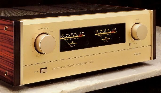
Accuphase E-305V
¥280,000(Released in November 1991)
Commentary
This pre-main amplifier is based on the E-305 and has been polished to a higher perfection.
Based on the development technology that ACPHASE has developed over many years, we have reconsidered the circuit and construction to pursue the same quality as a separate amplifier.
In the power amplifier section, an N-channel power MOS FET and a P-channel power MOS are applied to the element of the output stage.
Three FETs are connected in parallel to each other.
The parallel use of power MOS FETs makes it possible to extract sufficient power for low impedance.
The driver stage that drives the power MOS FET uses a cascode connection.
By suppressing the phase rotation as small as possible and reducing the voltage applied to the input part of the cascode stage, the performance of the element is drawn out, resulting in a wide band and wide linearity and power MOS.
Driving to the FET is ideal.
AccuPhase's unique complimentary service push-pull circuit is used for the input, and the input FET is cascode-connected.
All unit amplifiers for analog disk, high level, and power are connected by direct connection.
Each unit amplifier is stabilized by applying a strong DC servo to suppress DC drift.
A newly developed volume regulator is used.
The input level adjuster uses a mirror-finished resistor with low distortion. Depending on the mirror surface, it has excellent abrasion resistance. Moreover, there is no grease or anything that impairs sound quality between the brush and the resistor.
In addition, while the general volume structure has a fixed stator resistor and the brush is a slider, the E-305V attenuator has a structure in which the resistor rotates and the brush part is fixed and directly comes out as a terminal. This reduces the number of metal joints from five to three to improve sound quality.
This volume regulator is equipped with a gear mechanism and an electric motor for remote control.
Logic relay control is used to switch small signals such as the input selector.
By using a sealed relay containing nitrogen gas, aging is prevented, and wiring is possible at the shortest distance because it can be located locally.
This relay uses a gold-plated crossbar twin structure for the communication industry.
Comes with an input source and volume adjustable remote control.
Since the input selector switches relays electronically, this logic circuit is controlled by the commander so that there is no degradation in sound quality. In addition, the volume is adjusted by using a volume adjuster with a motor. The motor is magnetically shielded by silicon steel to minimize noise.
A micro computer is used for remote control demodulation.
It is equipped with an equalizer amplifier taking into consideration the characteristics of each cartridge of MM type and MC type.
Considering that the output voltage and output impedance of the MM cartridge are high at the time of MM input, it is composed of FET elements which can maintain post-input impedance over the whole frequency band.
Since the MC input receives very small signals with low impedance, a differential input circuit with low-noise elements is constructed to achieve low impedance of the NFB loop, enabling low-noise reproduction.
The preamp section and power amplifier section are separated, and a changeover switch and input / output terminals are mounted for use as an independent amplifier.
It uses the addition type active filter tone control used in full-fledged graphic equalizers.
It has a structure that emphasizes sound quality by allowing the original signal to pass straight through and adding or subtracting additional characteristics to the signal as needed.
By using a dedicated power supply and a constant voltage circuit for each of the preamplifier and power amplifier, interference through the power supply is prevented.
To reduce the negative effects of electrostatic coupling and electromagnetic induction, we have taken measures such as improving the internal structure and arrangement.
Eight inputs and two tape recorder inputs are available. Of these, two balance inputs, CD and Line, are available.
The output of the power amplifier can be monitored with a large power meter.
The meter uses a logarithmic compression type so that you can see a wide dynamic range at once.
You can switch between two A / B speakers, or you can connect a bi-wired speaker with an A + B position where the two speakers are connected in parallel, with separate networks for bass and treble.
.JPG)
.JPG)
.JPG)
.JPG)
.JPG)
.JPG)
.JPG)
.JPG)
.JPG)
.JPG)
.JPG)
Model Rating
| Type | Integrated Stereo Pre-Main Amplifier | |||||||||||||||||||||||||
| continuous average output (both channel operation, 20 Hz ~ 20 kHz, Distortion Factor 0.02%) |
4 ohm load : 180W/ch 8 ohm load : 130W/ch |
|||||||||||||||||||||||||
| Total Harmonic Distortion Factor (both channel operation) | 0.02% (4 to 16 ohm load, 0.25W to continuous output, 20 hz to 20 khz) | |||||||||||||||||||||||||
| IM Distortion Factor | 0.01% | |||||||||||||||||||||||||
| Frequency Response |
|
|||||||||||||||||||||||||
| Damping factor | 100 (8 ohm load, 50 Hz) | |||||||||||||||||||||||||
| Rated Input / Input Impedance |
|
|||||||||||||||||||||||||
| Rated Output / Output Impedance | Pre Output : 1.28V/200 Ω Tape Rec Output : 125mV/200 Ω (from AD) Headphones : 0.4 v, Applicable Impedance 4 ~ 100 Ω |
|||||||||||||||||||||||||
| Gain | Main Input → Output : 28 dB High Level Input → Pre Output : 20 dB AD Input (MM) → Tape Rec Output : 30 dB AD Input (MC) → Tape Rec Output : 60 dB |
|||||||||||||||||||||||||
| S/N, input conversion noise |
|
|||||||||||||||||||||||||
| Tone Controls | Bass : turnover frequency 300 Hz, ± 10 dB (50 Hz) Treble : Turnover frequency 3 kHz, ± 10 dB (20 kHz) |
|||||||||||||||||||||||||
| Subsonic Filter | 17 Hz, -12dB/oct | |||||||||||||||||||||||||
| Attenuator | -20dB | |||||||||||||||||||||||||
| Power Meter | Logarithmic Compression Peak Level Display Direct reading of output at dB scale and 8 Ω load |
|||||||||||||||||||||||||
| Load Impedance | 4-16 ω | |||||||||||||||||||||||||
| Semiconductors used | Transistors : 59 FET : 22 IC : 24 pcs Diodes : 69 |
|||||||||||||||||||||||||
| Power Supply | 100V/117V/220V/240V, 50Hz/60Hz | |||||||||||||||||||||||||
| Power Consumption | No Input : 65W Electrical Appliance and Material Control Law : 310W 8 Ω load at rated output : 490W |
|||||||||||||||||||||||||
| External Dimensions | 475 mm wide x 170 mm high x 418 mm deep | |||||||||||||||||||||||||
| Weight | 22.7kg | |||||||||||||||||||||||||
| Included : Remote Commander RC-8 | ||||||||||||||||||||||||||
| Remote Control Method | Infrared Pulse Method | |||||||||||||||||||||||||
| Power Supply | DC 3V | |||||||||||||||||||||||||
| Dry Battery | SUM-3 (IEC designation R6) 2 pieces | |||||||||||||||||||||||||
| Maximum External Dimensions | 64 mm wide x 149 mm high x 18 mm deep | |||||||||||||||||||||||||
| Weight | 140g (including dry batteries) | |||||||||||||||||||||||||