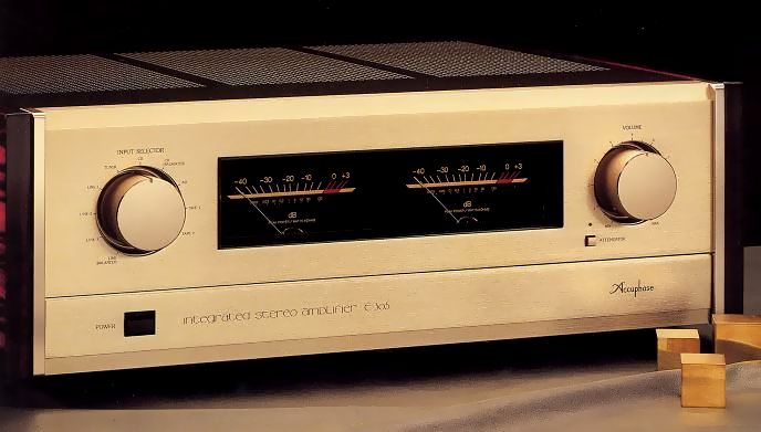
Accuphase E-305
¥270,000(Released in December 1987)
Commentary
This pre-main amplifier was developed for the new audio era by making use of the development technology and materials of the separate amplifier cultivated over many years.
A full-scale 3-amp configuration consisting of an equalizer amplifier for analog disks, a high-gain pre-amplifier and a power amplifier has been adopted to enhance the perfection of each.
The output stage of the power amplifier is 3 parallel push-pull with 6 transistors, and Pc (collector loss) is 130W per element, making up a powerful output stage with a total of 780W.
This realizes "low load drive" that can deliver sufficient power even for low load impedance.
MOS FET is used in the front stage of driving the output stage.
In addition, the input stage is a cascode system, and together with a constant current load, wide bandwidth and high linearity are realized.
The second stage differential amplifier circuit consists of a single-chip dual transistor as a complimentary service circuit, resulting in low noise and excellent stability.
All the unit amplifiers of each stage are connected directly from the analog disk input.
The problem of DC drift caused by direct connection is solved by stabilizing each unit amplifier with DC servo.
In order to suppress interference between unit amplifiers due to the power supply, electrostatic and electromagnetic induction, the transformer windings of the preamplifier and power amplifier are separated to prevent interference around the power supply, and a dedicated power supply is configured.
In addition, the preamp section is stabilized by a full-scale constant voltage circuit, and has been improved to the same level as an independent case amplifier.
In addition, it is carefully arranged and shielded against electrostatic and electromagnetic induction.
The equalizer amplifier section switches between the MC type and MM type according to the required gain.
A low-noise, high-gm FET is connected to a 3-parallel cascode and bootstrap differential circuit to achieve a stable circuit with excellent S/N. Especially for the MC cartridge with Oire force signal, 3-parallel reduces residual noise.
To prevent signal degradation caused by switching or routing of the signal path, the input section uses a method in which relays are installed where switching is necessary and controlled electronically by a logic circuit.
This relay uses a sealed type with cross-bar twin silver-palladium gold-plated contacts.
It has 8 input terminals and 2 balance terminals.
In addition, the built-in recording selector is independent of the input selector, so you can record FM broadcasts while listening to CDs.
It is also equipped with a copy switch that allows independent dubbing between sound recorders.
It is equipped with separate input / output terminals that can be used as an independent amplifier by electrically separating the preamplifier and the power amplifier.
For tone control, we have developed an additive active filter method which is also used in graphic equalizers.
In this method, the original flat signal passes straight through, another characteristic is created as necessary, and the signal is adjusted from the flat signal.
Equipped with a peak power meter of logarithmic compression peak indication type.
It includes a speaker selector that switches between two pairs of speakers, a mode switch that mixes the left and right sounds, a subsonic filter that cuts out the harmful ultra-low noise of analog disks, and a compensator that enhances the low-sound feel when the volume is low.
The front panel features a gold-style scratch hairline design with natural Persimmon sideboards on both sides.
.JPG)
.JPG)
.JPG)
Model Rating
| Type | Integrated Stereo Pre-Main Amplifier | |||||||||||||||||||||||||
| continuous average output (both channel operation, 20 Hz ~ 20 kHz, Distortion Factor 0.02%) |
4 ohm load : 180W/ch 8 ohm load : 130W/ch |
|||||||||||||||||||||||||
| Total Harmonic Distortion Factor | 0.02% (4-16 Ω load, dual-channel operation, 0.25W to continuous output, 20 hz to 20 khz) | |||||||||||||||||||||||||
| IM Distortion Factor | 0.01% | |||||||||||||||||||||||||
| Frequency Response |
|
|||||||||||||||||||||||||
| Damping factor | 100 (8 ohm load, 50 Hz) | |||||||||||||||||||||||||
| Rated Input / Impedance |
|
|||||||||||||||||||||||||
| Disk Max Input (1 kHz, 0.005% distortion) |
MM Input : 300 mVrms (Rec Out) MC input : 8.0 mVrms (Rec Out) |
|||||||||||||||||||||||||
| Rated Output / Impedance | Pre Output : 1.28V/200 Ω Tape Rec Output : 125mV/200 Ω (from AD) Headphones : 0.4 v, Applicable Impedance 4 ~ 100 Ω |
|||||||||||||||||||||||||
| Gain | Main Input → Output : 28 dB High Level Input → Pre Output : 20 dB AD Input (MM) → Tape Rec Output : 29 db AD Input (MC) → Tape Rec Output : 60 dB |
|||||||||||||||||||||||||
| S/N, input conversion noise |
|
|||||||||||||||||||||||||
| Tone Controls | Bass : turnover frequency 300 Hz, ± 10 dB (50 Hz) Treble : Turnover frequency 3 kHz, ± 10 dB (20 kHz) |
|||||||||||||||||||||||||
| Loudness Compensator | + 6 dB (100 Hz, Volume -30dB) | |||||||||||||||||||||||||
| Subsonic Filter | 17 Hz, -12dB/oct | |||||||||||||||||||||||||
| Attenuator | -20dB | |||||||||||||||||||||||||
| Power Meter | Logarithmic Compression Peak Level Display Direct reading of output at dB scale and 8 Ω load |
|||||||||||||||||||||||||
| Load Impedance | 2 to 16 ohms | |||||||||||||||||||||||||
| Semiconductors used | Transistors : 77 FET : 34 IC : 20 pcs Diode : 78 |
|||||||||||||||||||||||||
| Power Supply | 100V/117V/220V/240V, 50Hz/60Hz | |||||||||||||||||||||||||
| Power Consumption | No input : 60W Electrical Appliance and Material Control Law : 310W 8 Ω load at rated output : 490W |
|||||||||||||||||||||||||
| External Dimensions | Width 475x Height 170 (including legs) x Depth 375 mm | |||||||||||||||||||||||||
| Weight | 20.5kg |