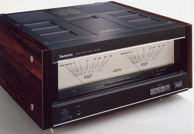
Technics SE-A100
¥ 300,000 (released in 1985)
¥ 279,000 (revised in 1989)
Commentary
Stereo power amplifier equipped with ClassAA circuit.
In the ClassAA circuit, the voltage control amplifier and the current drive amplifier are respectively handled by separate amplifiers. This frees the voltage control amplifier from the current supply and enables voltage control faithful to the input signal, thereby realizing low distortion. The current drive amplifier can stably supply the current required for speaker drive, and has acquired excellent speaker drive capability.
The SE-A100 has a VC-4 configuration with two voltage control amplifiers and two current drive amplifiers for the left and right, for a total of four.
The voltage control amplifier employs a Darlington configuration with a differential amplifier input stage using one chip dual FET and a Pc150Wx2ch output transistor, and is a complete A-class amplifier that realizes ultra-low distortion close to the limit of measured values.
The current drive amplifier consists of a FET differential amplifier input, a high-speed amplitude amplifier stage equipped with a newly developed feed-forward type bootstrap power supply, and a Pc450Wx2/ch 4-stage Darlington output stage using 3-parallel output transistors. It supplies a large current at 50A / μ s to obtain a strong power.
The power supply section has a 3-transformer configuration, equipped with a power transformer for the left and right current drive amplifiers and a transformer for the left and right voltage drive amplifiers. Fully symmetrical construction is employed to eliminate interference between the left and right channels. In addition, the power supply capacitor is equipped with an electrolytic capacitor of 91,200 μ F in total.
The power transformer uses oxygen-free copper wire and is equipped with high-density and high-efficiency technology by the perfectly aligned winding method to improve regulation. In addition, it is sealed with special resin in a total of three layers of magnetic shielding case to reduce adverse effects such as mechanical vibration and magnetic flux leakage.
In order to suppress adverse effects of electromagnetic radiation from sections that handle large current such as the output stage and power supply section, a unique concentrated power block that integrates the output stage and power supply section is adopted to suppress the effects of electromagnetic fields.
The top plate is 3 mm thick and 2.3 kg weight class, and magnetic radiation and mechanical vibration are suppressed by the adoption of 2 mm thick high rigidity chassis and 2 mm thick insulator rubber at the bottom of the transformer.
In addition, a punching net with a high aperture ratio is used for the top plate and bottom plate, and high heat radiation effect is obtained with a radiator whose shape is determined by computer analysis and a large leg of 21 mm high and φ 50 mm the bottom.
Oxygen-free copper bus bars 2 mm thick and 10 mm wide are arranged for the earth line, and LC-OFC cord is used for the wiring material.
An electronic speaker selector is used, gold-clad contacts are used for the switching relay, and the power supply after turning off is equipped with the last one memory function to hold the selected contents.
Equipped with a large power meter that can read directly from 0.0001W to 300W.
In addition, 10 mm thick bronze glass is used for the front.
Equipped with a VC-4 indicator to check the operation of the voltage control amplifier and current drive amplifier.
Equipped with DC / normal 2-way input terminal.
The power cable is made of 50-core oxygen-free copper wires and has an outer diameter of φ 7.4 mm.
Oxygen-free copper pin cord with gold plated terminals is included.
.JPG)
.JPG)
Model Rating
| Type | Stereo power amplifier | ||||
| Rated Output (20 Hz ~ 20 kHz) | 240W + 240W (4 Ω, 0.002%) 200W + 200W (6 Ω, 0.001%) 170W + 170W (8 Ω, 0.0007%) |
||||
| Dynamic Power (IHF) | 600W + 600W (2 Ω) / 600W + 600W (2 Ω ± 60 ° Reactance Load) 400W + 400W (4 Ω) / 400W + 400W (4 Ω ± 60 ° Reactance Load) 275W + 275W (6 Ω) / 275W + 275W (6 Ω ± 60 ° Reactance Load) 225W + 225W (8 Ω) / 225W + 225W (8 Ω ± 60 ° Reactance Load) |
||||
| Distortion factor (-3dB) |
|
||||
| Frequency characteristic | 0.8 Hz ~ 150 kHz + 0 -3dB 20 Hz ~ 20 kHz + 0 -0.1 dB |
||||
| Output bandwidth | 5 Hz to 100 kHz (cpo-3 dB, 0.01%, 8 Ω) | ||||
| Signal-to-noise ratio | 120dB(IHF'66) 93dB(EIAJ) |
||||
| Residual noise voltage | 300 μ V or less (Lin.) 50 μ V or Less (IHF-A) |
||||
| Input Sensitivity / Impedance | 1.2V/47k Ω | ||||
| Damping factor | 120 (8 Ω) | ||||
| Meter indication range | 0.0001W ~ 300W (8 Ω) -60dB to + 2 dB |
||||
| Meter indication accuracy | ± 3 dB (-40dB or more) ± 5 dB (less than -40dB) |
||||
| Meter attack time | 100 μ s | ||||
| Recovery time | 300ms | ||||
| Power consumption | 400W | ||||
| Pwer | 100 VAC, 50/60Hz | ||||
| External dimensions | Width 476x Height 209x Depth 475 mm | ||||
| Weight | 33.7kg |