SANSUI CD-10
¥ 109,000 (around 1975)
Commentary
A channel divider that pursues basic characteristics and multiple functions.
The filter circuit consists of all stages of emitter-follower circuit with 2 low-noise transistors of PNP-NPN.
In particular, the buffer amplifier at the input stage has an L/R4 circuit structure and is designed to take advantage of the inherent performance of the buffer amplifier to achieve a high SN ratio and low distortion factor.
In addition, since the input / output circuit of each frequency selector stage is 0 V potential in ± 2 power supply system, there is no click noise even if any frequency selector is switched during use.
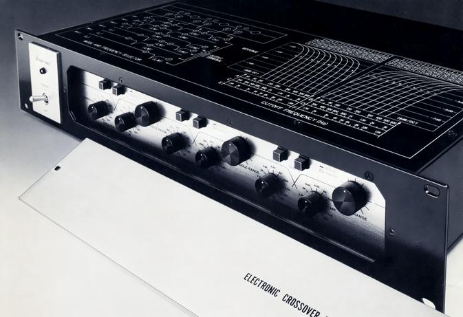
The CD-10 supports up to 4-way systems in order to use a wide range of bandwidth by adding a super-tweeter and a subwoofer to the 3-way system. In addition, the CD-10 can be divided into six frequency bands from 2-way to 4-way by combining four bands divided into low, mid-low, mid-high, and high bands, using the mode selector on the back panel.
You can choose from 11 levels of crossover frequencies : from 60 hz to 600 hz for low-mid-low, from 300 hz to 3 khz for low-mid-high, and from 1.5 khz to 15 khz for high-mid-high.
Moreover, since the crossover frequencies on the low and high sides of each split band can be independently changed, the overlap portion can be freely adjusted in addition to the normal -3dB cross point.
There are two sharp cut-off slopes, 18dB/oct. and 12dB/oct., which can be switched at both ends of the low and high frequency side of each band to be crossed. The -3dB point of each cut-off slope is exactly the same, so that a characteristic cut-off frequency can be obtained under any condition.
As with the frequency selector, the selector switch is located on the front panel and can be selected while listening to the actual sound.
The level of each band can be individually adjusted. The low band is on the back panel, and the middle and low band, middle and high band are on the front panel. It can be used for all types of units such as cone type and horn type units, efficiency differences, etc.
Low booster enables low-frequency compensation.
The knob can be installed on the rear panel to compensate 0 to 8 dB at 20 Hz in 10 steps. Moreover, the turnover frequency can be switched between 60 Hz and 100 Hz to improve the sense of volume in the ultra low range, which is often lacking.
It adopts the same design as BA-1000 and QSD-1, and can be mounted in professional rack as it is.
.JPG)
.JPG)
.JPG)
.JPG)
Model Rating
| Type | Channel divider | ||||||
| Circuit system | 2, 3, 4 Way NF Filter | ||||||
| Maximum power output | 8 V (THD 0.1% or less) | ||||||
| Rated output | 5V | ||||||
| Total harmonic distortion factor | 0.008% or Less (at Rated Output) | ||||||
| Signal-to-noise ratio | 90 dB or more (at rated output) | ||||||
| Input impedance | 150k Ω | ||||||
| Load impedance | 10k Ω | ||||||
| Cut-off frequency (+ / - 10 per cent) |
|
||||||
| Cutoff characteristic | 18dB/oct., 12dB/oct. (low band side, high band side) |
||||||
| Low boost | 0 to + 8 dB (20 Hz) | ||||||
| Low-boost turnover | 60 Hz, 100 Hz | ||||||
| Power consumption | 10W | ||||||
| External dimensions | Width 482x Height 88x Depth 305 mm | ||||||
| Weight | 6.4kg |