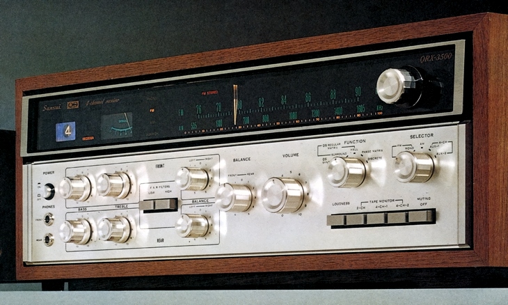
SANSUI QRX-3500
¥ 135,000 (around 1973)
Commentary
A top-of-the-line 4-channel receiver with built-in newly developed QS Barrio matrix circuit that supports all 4-channel systems.
The QS Synthesizer / Decoder section incorporates a newly developed QS Barrio matrix circuit in addition to synthesizer / decoder functions, phase shifters and phase matrix functions.
The 90 ° phase shifter is designed to solve the problem of the conventional matrix circuit in which the phases of the two rear speakers were reversed. On the decoder side, the phases of the left rear speakers are shifted by -90 °, and the phases of the right rear speakers are shifted by + 90 °. The phases between the rear speakers are On the encoder side, the reverse operation is performed.
The newly developed QS Barrio matrix circuit is an application of an acoustic phenomenon called directional masking. By instantaneously changing the matrix coefficient of the input signal, the reproduced signal is controlled so that the directivity becomes clear, and the separation is improved. Theoretically, the QS Barrio matrix circuit can obtain infinite separation between each channel by selecting the control level of the matrix coefficient, but from the viewpoint of music reproduction, it is adjusted to the optimum level for audibility. This circuit is controlled by using a phase discriminator that detects the phase of the input signal.
A 2-4 conversion encoder circuit is included as a synthesizer function, and special processing is applied to the reproduction of the normal 2-channel source so that the QS Barrio matrix circuit can be effectively converted into 4 channels.
Also, by adding a phase matrix circuit, SANSUI's original front / back logic is realized, and the 4-channel source created by SQ method can be reproduced with sufficient separation.
It has a 4-channel aux input terminal that can be used with 4-channel tape decks or CD-4.
The power amplifier section uses a pure complimentary service circuit directly connected to all stages.
The protective circuit is equipped with a quick-cut fuse and a relay to prevent pop noise during power ON/OFF.
A 2-stage direct-coupled NF-type equalizer circuit is used for the preamplifier section.
In addition, the tone control is a click step type, and the front and rear can be controlled independently.
For the front end of the tuner section, a dual gate MOS type FET and a precision four series varicon are adopted.
The IF stage combines two stages of two element ceramic filters and an IC, and the multiplex circuit is also designed to improve stability by carefully selecting parts.
The power supply section is equipped with a large transformer, large capacitor, and NF-type constant voltage circuit.
Equipped with functions such as low / high filter, loudness and balance control.
Equipped with FM input sensitivity change-over switch.
LOC is used for short distances with strong signals, and DIST is used for long distances.
Equipped with a muting switch, noise between stations of FM broadcasting can be reduced.
Volume and balance can be controlled from a remote location by using the optional remote controller.
.jpg)
| 1. QS Synthesizer / Decoder 4. Tuner section 7. Power Switch 10. Low / High Filter 13. Function Switches 16. Tape Monitor Switch 19. Digital indicators 22. AC outlet |
2. Power amplifier section 5. Power Supply 8. Headphone jack 11. balance control 14. Selector switch 17. Muting switch 20. Antenna Terminal 23. Ferrite bar antenna |
3. Preamplifier Section 6. Remote Controller 9. Tone Control 12. Volume Switch 15. Loudness Switch 18. Tuning Knob 21. FM sensitivity selector switch |
Model Rating
| Type | 4-channel receiver |
| Synthesizer Unit | |
| Synthesizer / decoder | Sansui QS Regular Matrix Circuit (built-in QS Barrio matrix circuit) |
| Pre-Main Amplifier Section | |
| Music Power (IHF) | 180W (4 Ω, 1 kHz) |
| Effective power | 22W/22W/22W/22W / 22 w / 22 w (8 Ω, each channel operation, 1 khz) 15W + 15W + 15W + 15W + 15W (8 ohm, 4-channel operation, 20 hz to 20 khz) |
| Total harmonic distortion factor | 0.5% or Less (Rated Output) |
| Cross modulation distortion factor | 0.5% or Less (70 Hz : 7 kHz = 4 : 1 SMPTE at Rated Output) |
| Power Band With (IHF) | 10 Hz to 33 kHz |
| Frequency characteristic | 30 Hz to 30 kHz |
| Input Sensitivity / Impedance | Phono : 2.5mV/50k Ω (1 kHz at rated output) |
| Phono maximum allowable input | 100 mV (THD 0.5% or less) |
| Hum and noise (IHF) | Phono : 70 dB or more |
| FM Tuner Section | |
| Sensitivity (IHF) | 2.2 μ V |
| Selectivity | 50 dB or more |
| Total harmonic distortion factor | mono:0.4% stereo:0.6% |
| Signal-to-noise ratio | Mono : 65 dB or higher |
| Stereo separation | 35 dB or More (1 kHz) |
| Capture ratio | 2 dB or less (IHF) |
| Image rejection | 75 dB or more |
| <AM Tuner Section> | |
| Sensitivity | 50dB/m (bar antenna) |
| Selectivity | 25 dB or more |
| <General> | |
| Semiconductor used | Transistor : 110 units Diode : 61 Units FET : 3 IC : 1 Zener diode : 3 pcs |
| Power consumption | 110W (rated) 300 VA (max) |
| External dimensions | Width 526x Height 181x Depth 350 mm |
| Weight | 18.5kg |
| Sold Separately | Wired Remote Controller QBL-100 (¥ 6,900) |
.jpg)