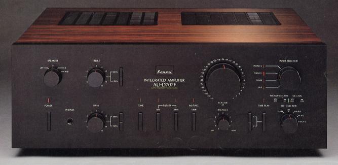
SANSUI AU-D707F
¥ 108,000 (released in 1980)
Commentary
This pre-main amplifier is equipped with a newly developed super feed-forward system that transcends the limits of NFB.
In order to supplement the NFB technology used in conventional amplifiers and to further reduce distortion, a newly developed super feed-forward system is incorporated.
This circuit is based on the feed-forward theory devised by H. S. Black in 1928. At Sansui, we explored the possibility of practical use in 1975, but it crashed into a wall and was interrupted. In 1978, we restarted our research but failed. In 1980, we obtained a hint that NFB technology could be used in combination, and finally completed this circuit.
This feed-forward circuit takes out only the distortion component from the original signal, combines it with the output in opposite phase, and cancels the distortion. However, this circuit is only theoretically possible and has many problems to overcome, so it was considered a phantom theory. Therefore, the Super Feed-forward system combines the advantages of both NFB and feed-forward.
The NFB mainly works to improve low-frequency distortion and also takes out anti-phase distortion for feed-forward. In addition, an error collection amplifier for feed-forward is installed, and computer technology is used to develop an output summing network capable of canceling distortion even in response to 2-pole compensation, making it possible to eliminate distortion over a wide band.
This super feed-forward system enables designs with low NFB, improves amplifier stability and reduces TIM distortion to almost 0.
It is equipped with the diamond differential circuit adopted in the AU-D series.
The diamond differential circuit is a dual complimentary service differential connection consisting of two pairs of upper and lower differential circuits. It is mounted on the pre-drive stage to deliver the necessary drive current to the power stage accurately even for transient and complex peak inputs such as music signals.
The 2-pole phase compensation circuit extends the operating range of the NFB and realizes excellent high-speed response to input signals.
It is designed to be simple and straight, and the signal flow is very short and simple. At the same time, three dimensional wiring is carried out to create the shortest signal path.
Furthermore, by adopting a heat pipe for heat dissipation, it is possible to develop the pattern from input to output along the flow of the circuit diagram in an ideal portable type for the printed circuit board configuration. Therefore, the power stage and driver stage can be set close to each other, which was difficult with the conventional heat sink. Furthermore, the two transistors constituting the push-pull output circuit can be installed close to each other, eliminating the need to draw wires near the output transistor through which a large amount of power flows.
A twin relay speaker switch is used to switch between speakers A and B to prevent the output line from being routed.
By utilizing the know-how acquired through the AU-D907Limited and using a large amount of wood bonnet, bronze-plated screws, and NM elements, we are thoroughly implementing designs that are less affected by magnetic strain, including the substrate and chassis structure.
The tone amplifier is omitted and the configuration consists of two amplifiers, a high-gain equalizer amplifier and a power amplifier.
The EQ uses a low-noise, high-gm dual FET for the first stage, and a push-pull drive pure complimentary service SEPP output with two differentials and current differentials with a current mirror.
A DC servo is used to remove the output capacitor while maintaining the stability of the DC region.
A newly developed linear servo regulator is used for the power supply dedicated to the equalizer.
By supplying a constant bias current in the circuit, this stabilized power supply can provide a stable response to transient loads, enabling a clean and stable power supply at all times.
For the MC cartridge, it is equipped with an MC head amplifier that adopts a symmetrical circuit with two differential stages.
With this MC head amplifier, you can select between the High position (0.1mV/100 Ω) and the Low position (0.25mV/100 Ω) by installing an input gain switching switch so that the output can be adjusted depending on the type of cartridge.
The power supply section is of two independent power source system with two windings and two power sources.
The block capacitor employs a high-speed capacitor that is low-impedance by low-magnification etching and has excellent follow-up capability even in transient charge and discharge.
In addition, a fast recovery diode with a fast switching speed is used for the rectifier diode to improve regulation response.
It is equipped with a simple tone control circuit composed of CR.
Because it is a simple system without an equalizer or power amplifier, it is designed so that the tone control does not work at the volume position of -6dB to 0 db (at full power). Therefore, the saturation does not exceed the amplification of the amplifier at full power unlike the conventional system.
Equipped with subsonic and supersonic filters, two circuit tape monitor, recording selector / copy function, audio muting, balance control, input selector with encoder, etc.
There were 2 kinds, black model with Rosewood style bonnet and silver model with white oak style bonnet.
.JPG)
Model Rating
| Type | Super Feedforward & DD/DC Amplifier |
| Power Amplifier Unit | |
| Effective power | 95W + 95W (8 ohm, 10 hz to 20 khz, THD 0.005%) 95W + 95W (8 ohm, 1 kz, 0.003% THD) |
| Total harmonic distortion factor (10 Hz to 20 kHz at effective output) | Not more than 0.005% |
| Intermodulation Distortion Factor (60 Hz : 7 kHz = 4 : 1, SMPTE) | Not more than 0.008% |
| Output Bandwidth (IHF, both channel operation, THD 0.02%) | 5 Hz to 80 kHz |
| Damping factor (new IHF, 20 Hz to 20 kHz) | 100 (8 Ω) |
| Frequency Response (1W) | DC ~ 300 khz + 0 -3dB |
| Signal-to-noise ratio (A network) | 110 dB or more |
| Envelope distortion | Below the measurement limit |
| TIM Strain (Sawtooth method) | Below the measurement limit |
| Slew rate | ± 200 v / μ sec (8 Ω) |
| Inside slew rate | ± 300 v / μ sec (8 Ω) |
| Rise time | 0.8 μ sec |
| Preamplifier Section | |
| Input Sensitivity / Input Impedance (1 kHz) | Phono1, 2 mm : 2.5mV/47k Ω Phono1, 2 mc (high/low) : 100 μ V, 250 μ V/100 Ω Tuner, AUX, Tape Play1, 2 : 250mV/27k Ω |
| Phono maximum allowable input (1 kHz, THD 0.01%) | MM:200mV MC:25mV |
| Output Level / Impedance (1 kHz) | Tape Rec : 250 mv (47k Ω) / 600 Ω |
| Total harmonic distortion factor | Phono1, 2 mm : 0.005% or less (20 Hz to 20 kHz, 5 V) |
| RIAA Deviation (MM) | 20 Hz to 20 kHz ± 0.2 dB |
| Signal-to-noise ratio (A network) | Phono1, 2 mm : 90 dB or more Phono1, 2 mc : 74 dB or more |
| Phono input equivalent noise (A network, short circuit) |
Phono1, 2 mm : -142dBV Phono1, 2 mc : -154dBV |
| Channel separation | Phono1, 2 mm : 60 dB or more Phono1, 2 mc : 50 dB or more Tuner, AUX, Tape Play : 80 dB or higher |
| Tone control | Bass : + 6 to -8dB at 50 Hz Treble : ± 6 dB at 10 kHz |
| Tone selector | Bass : 150 Hz, 300 Hz Treble : 3 kHz, 6 kHz |
| Filter | Low : 16 Hz (-3dB, 6dB/oct.) High : 20 kHz (-3dB, 6dB/oct.) |
| Audio Muting | -20dB |
| <General> | |
| Rated power consumption (Electrical Appliance and Material Control Law) | 250W |
| External dimensions | Width 445x Height 163x Depth 403 mm |
| Weight | 14.0kg |