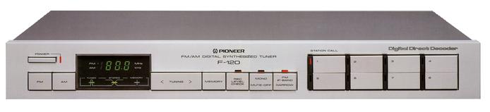
Pioneer F-120
¥ 45,000 (released in 1982)
Commentary
An FM/AM tuner equipped with a D. D. (Digital Direct) decoder developed with Pioneer's tuner technology.
Pioneer has developed and adopted its own D. D. decoder to digitally detect and demodulate signals and to completely eliminate distortion and noise generation.
This circuit is a simple method in which a signal converted into a 1.26 MHz pulse by a pulse converter is sent directly to a multiplier for L/R separation, and the signal is multiplied by a 38 kHz subcarrier made from a 19 kHz pilot signal. Since the FM signal remains a digital signal after the pulse converter until the output, deterioration of the S / N ratio and distortion are suppressed.
There is also no need for filters that can cause signal loss or distortion.
The resulting subcarrier is a clean sine wave that does not adversely affect the audio signal, so it can produce a clean, high-purity signal.
This D. D. decoder takes note of the principle of a tuner that multiplies an FM signal (analog signal) and a subcarrier (square wave) for demodulation. It was born from the bold idea that if you multiply an FM signal into a pulse wave and a subcarrier into a sine wave, the result will be the same. This method realizes excellent characteristics such as SN ratio, distortion rate, separation, and various interference rejection capabilities.
The parts are carefully selected to improve the sound quality.
First of all, the D. D. decoder is completely LC-filterless from pulse conversion to output to eliminate distortion caused by the LC filter itself.
In the low-pass filter section of the final stage, an active filter with sharp characteristics is used in place of the conventional passive filter using coils to prevent deterioration of sound quality caused by coils, etc.
We have also developed and adopted a low-distortion semiconductor capacitor for the high-frequency section, as well as a copper foil styrene capacitor and a fast recovery diode with good rectification characteristics.
In addition, oxygen-free copper wire is used for wiring.
A linear front end is used for the front end to improve RF intermodulation characteristics.
It uses a twin varicap tuning element and a unique balance hold capacitor system to achieve high reception performance.
We are also working to improve the RF intermodulation characteristics by using IDMOS FET with improved characteristics as an RF amplifier.
In addition, a newly developed FET balanced mixer has been incorporated to achieve high stability and to improve the ability to eliminate interference such as image interference.
Taking note of the fact that the difference between the frequency on the antenna side and the oscillation frequency on the local side causes distortion and degrades sound quality, we have installed a newly developed tracking oscillator circuit in order to maintain a linear relationship between both frequencies and suppress distortion.
MOS FET is used in parallel for the first stage amplifier of the IF to obtain high gain and high SN ratio.
In addition, a crystal oscillator circuit is adopted for the oscillation circuit of the frequency conversion section (converted to 1.26 MHz by the second local oscillator) when sending signals to the D. D. decoder after the detection stage. This circuit improves stability and SN while eliminating drift due to environmental changes such as temperature and humidity.
In addition, two stage switching of the IF band is adopted to always obtain the highest quality.
In the conventional quartz synthesizer type PLL circuit, the reference frequency was set at 12.5 kHz, and the sound quality was deteriorated as residual noise in the audible band. However, by setting the reference frequency to 25 kHz using the original pulse swallow method and moving it out of the audible band, the cause of residual noise is eliminated.
Static control method is adopted for digital control signal transmission method.
In general, in order to simplify the transmission of complex signals, a dynamic control method was adopted in which multiple pieces of information are transmitted on a single signal line. However, in order to prevent noise generated when information is combined, only one piece of data is transmitted on a single signal line to prevent SN degradation.
The preset station is equipped with an FM + AM random 8-station preset switch and an FM/AM each 8-station preset switch.
It has a convenient design that can be used by switching to either one with a single switch on the rear panel.
The AM section uses a loop antenna and takes into consideration elements and circuits such as a wide-range ceramic filter and a 9 kHz notch filter.
.JPG)
.JPG)
Model Rating
| Type | FM/AM tuner with D. D. decoder | ||||
| FM Tuner Section | |||||
| S/N ratio 50 dB sensitivity | Mono : 1.8 μ V, new IHF 16.2 dBf Stereo : 21.0 μ V, new IHF 37.7 dBf |
||||
| Practical sensitivity (Narrow, 75 Ω) | Mono : 0.95 μ V, new IHF 10.8 dBf | ||||
| SN ratio at 80 dBf input | mono:96dB stereo:88dB |
||||
| Harmonic distortion factor |
|
||||
| Capture ratio | Wide:0.8dB Narrow:2.5dB |
||||
| Effective selectivity | Wide:30dB(400kHz) Narrow:60dB(300kHz) |
||||
| Stereo separation | Wide : 65 dB (1 kHz), 50 dB (20 Hz to 10 kHz) Narrow : 40 dB (1 kHz), 40 dB (20 Hz to 10 kHz) |
||||
| Frequency characteristic | 20 Hz to 15 kHz + 0.2 -0.8 dB | ||||
| Image interference ratio | 80dB | ||||
| IF interference ratio | 100dB | ||||
| Spurious interference ratio | 90dB | ||||
| AM suppression ratio | 70dB | ||||
| Subcarrier suppression ratio | 60dB | ||||
| Muting action level | 5 μ V (25.2 dBf) | ||||
| Antenna input impedance | 300 Ω Balanced Type 75 Ω Unbalanced Type |
||||
| <AM Tuner Section> | |||||
| Practical sensitivity | Bar antenna : 55 dB μ / m External antenna : 15 μ V |
||||
| Selectivity | 30dB | ||||
| Signal-to-noise ratio | 50dB | ||||
| Image interference ratio | 40dB | ||||
| IF interference ratio | 65dB | ||||
| <General> | |||||
| Output Level / Impedance | FM (100% modulation) : 650mV/900 Ω AM (30% modulation) : 150mV/900 Ω |
||||
| Power supply voltage | 100 VAC, 50Hz/60Hz | ||||
| Power consumption | 14W | ||||
| External dimensions | Width 420x Height 61x Depth 317 mm | ||||
| Weight | 4.0kg | ||||