Pioneer M-75
¥ 135,000 (around 1980)
Commentary
This is a stereo power amplifier designed to reduce distortion and provide high power with ample room.
The circuit uses a first stage differential current mirror load, 3-stage Darlington, parallel push-pull, and pure complimentary service OCl circuit.
In addition, the DC amplifier configuration without the capacitor from the NFB circuit provides flat phase characteristics over a wide band.
In order to eliminate interference between the left and right channels, the circuit of the left and right channels is structurally separated, and the power supply section is equipped with a large L/R independent two power transformer and a 22,000 μ Fx4 large-capacity capacitor, giving sufficient consideration to the routing of internal wiring.
A 20mm-wide and 2mm-thick pure copper plate is used for grounding wiring from the capacitor. On the hot side, an extra-thick 14th wire (2.03 φ wire) with a resistance value 1/4 of that of the conventional thick wire is used. The copper foil on the board is doubled to 70 μ m, reducing impedance and eliminating power loss and improving response to sharp pulses.
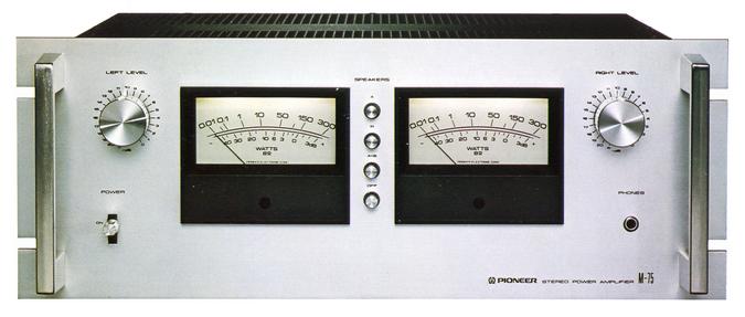
It uses a power meter that can directly read the peak output of music in watts.
0.01W to 300W (8 Ω) are displayed. Since there is no logarithmic compression circuit, the output can be read directly without switching.
Equipped with an L/R-independent 1-dB-step input level controller and a speaker selector switch that can be switched Off, A, B, or A + B.
.JPG)
Model Rating
| Stereo power amplifier | |
| Circuit system | First stage differential current mirror load 3-stage Darlington parallel push-pull Pure complimentary service OCL circuit (DC-amplifier configuration) |
| Effective power (Both channel drive, 20 Hz to 20 kHz) |
180W + 180W (4 Ω) 150W + 150W (8 Ω) |
| Harmonic distortion factor (20 Hz to 20 kHz, 8 Ω) |
Effective power : 0.01% At 75W output : 0.01% 0.01% at 1W output |
| Cross modulation distortion factor (50 Hz : 7 kHz = 4 : 1, 8 Ω) |
Effective power : 0.01% 75W output : 0.005% 0.005% at 1W output |
| Output Bandwidth (IHF, both channel drives) | 5 Hz to 35 kHz (Distortion Factor 0.01%) 5 Hz ~ 60 kHz (Distortion Factor 0.05%) |
| Frequency characteristic | 5 Hz ~ 100 kHz + 0 -1dB at 1W Output |
| Input terminal | Input : 1V/50k Ω |
| Output terminal | A / B : 4 Ω ~ 16 Ω A + B : 8 Ω ~ 16 Ω |
| Damping factor | 100 (20 Hz ~ 20 kHz, 8 Ω) |
| Signal-to-noise ratio | 115 dB (IHF, A-network, short circuit) |
| Semiconductor used | IC : 2 Transistor : 61 Diode, Other : 65 pcs |
| Power supply voltage | 100 V, 50Hz/60Hz |
| Power consumption (Electrical Appliance and Material Control Law) | 330W |
| Maximum Power Consumption | 900W |
| AC outlet | Non-linked : 1 system |
| External dimensions | Width 480x Height 187x Depth 445 mm |
| Weight | 24.5kg |
| EIA standard rack mounting unit | 4U |