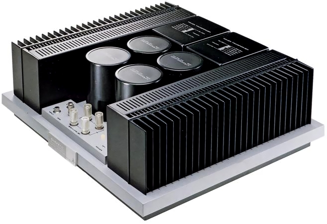
Pioneer M-22
¥ 120,000 (around 1980)
Commentary
Class A stereo power amplifier with a die-cast radiator and a die-cast chassis.
Class A operation is adopted for all stages.
In class A operation, a large amount of idle current is supplied to the transistor even when there is no signal, and only the operating range with good linearity of the transistor is used.
In class A operation, the power utilization factor is low and the amount of heat generation increases. However, since the two push-pull transistors are amplified with the same waveform in both upper and lower to obtain the combined output, switching distortion and crossover distortion that cannot be avoided in class B amplifier do not occur.
The class A operation circuit of the M-22 is a DC amplifier configuration without the capacitor of the NFB circuit. By this DC configuration, there is no time constant formation of the NFB loop, a flat phase characteristic can be obtained up to the ultra-low frequency band, and stable NFB operation can be obtained.
With all stages of A-class operation and this DC amplifier configuration, it achieves high and low frequency characteristics without distortion.
The power supply section uses a large L/R-independent transformer and a 33,000 μ Fx4 capacitor.
The construction of the whole amplifier, including the power supply section, is symmetrical. Two independent L/R power relays are used for the protection circuit. In addition, we pay attention to the routing of internal wiring to eliminate interchannel interference.
A pure copper plate is used for the ground line from the electrolytic capacitor to the speaker terminal.
To protect speakers and transistors in the event of an accident, a highly reliable protection circuit composed of power relays and fast response electronic circuits is built in.
The power relay has two contacts connected in parallel to improve reliability.
Model Rating
| Type | Stereo power amplifier |
| Circuit system | Differential 2-Stage, PP Drive, 2-Stage Darlington, Parallel PP Pure complimentary service OCL (Class A operation, DC-amplifier configuration) |
| Effective output (both channel drive) | 30W + 30W (10 Hz to 30 kHz, 8 Ω) |
| Harmonic distortion factor (10 Hz to 30 kHz, 8 Ω) |
Effective power : 0.01% 0.005% at 15W output 0.005% at 1W output |
| Cross modulation distortion factor (50 Hz : 7 kHz = 4 : 1, 8 Ω) |
Effective power : 0.005% 0.003% at 15W output 0.003% at 1W output |
| Output Bandwidth (IHF, both channel drives) | 5 Hz ~ 100 kHz (Distortion Rate 0.01%) |
| Frequency characteristic | 2 Hz ~ 150 kHz + 0 -1dB at 1W Output |
| Input terminal | Input : 1V/50k Ω |
| Output terminal | Speaker : 8 Ω |
| Damping factor | 60 (20 Hz ~ 20 kHz, 8 Ω) |
| Signal-to-noise ratio (IHF, A-network Short circuit) |
106dB |
| Semiconductor used | Transistor : 44 pcs Diode, other : 62 pcs |
| Power supply voltage | 100 V, 50Hz/60Hz |
| Power consumption | 240W (Electrical Appliance and Material Control Law) |
| External dimensions | Width 420x Height 153x Depth 370 mm |
| Weight | 22.0kg |