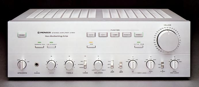
Pioneer A-900
¥ 135,000 (released in 1979)
Commentary
Pre-main amplifier with non-switching amplifier.
A non-switching amplifier is used for the circuit system of the power amplifier section.
This method uses a high-speed bias servo circuit to control the bias current according to the input signal, thereby eliminating switching operation and suppressing switching distortion.
Equipped with a line straight-through switch, you can pass not only a tone circuit but also a Mode switch and a balance volume, and connect an equalizer amplifier and a power amplifier directly.
When this switch is turned on, the Bass, Treble, Mode and Balance indicators turn off, indicating that the circuit has been canceled.
A non-coupling capacitor configuration is adopted in which all coupling capacitors in the signal system from the signal inlet to the signal outlet are eliminated.
For this reason, we have installed DC servo circuits in all stages of the MC head amplifier, equalizer amplifier and power amplifier. Especially in the MC head amplifier, we have adopted a new DC servo circuit (PAT. P.) a high SN ratio.
By eliminating magnetic materials from the lead wires of resistors and condensers that affect sound quality, and by using copper lead resistors and brass terminal electrolytic capacitors, hysteresis distortion caused by magnetic materials is eliminated.
The small signal circuit board (MC amplifier, equalizer amplifier) is equipped with independent constant-voltage power supplies for both the left and right sides. The large signal circuit board (power amplifier) is also equipped with a direct power supply system incorporating a dedicated constant-voltage power supply. This eliminates the need for cord routing and greatly reduces impedance.
In addition, a total of six independent secondary windings of three power transformers are used for each circuit to prevent interference between the circuits.
As for the power supply for the DC servo circuit, the MC head amplifier and the equalizer amplifier boards each use a constant-voltage power supply independently for the left and right sides. The power supply to this board is already a double-lock power supply that passes through another constant-voltage power supply once. Thus, even if there is some voltage fluctuation due to the input signal in the constant-voltage power supply of the first stage, there is almost no fluctuation in the second stage. Also, the power supply for the DC servo is separate for the power amplifier board, and it has a total of 6 pairs and 12 constant-voltage power supplies.
A relay is used to switch the signal path to minimize the wiring distance, and the input / output terminals are integrated with the board to improve reliability and stability.
The control circuit for relay switching is a logic circuit using an IC. Even when the power switch is turned off, the last state of use is stored in memory. Also, when the power supply to the power plug is lost, the memory is stored for three days. When the memory is turned off after three days, when the power is turned on, the Function is Tuner, and the Line Straight is on.
The MC head amplifier uses a super-low-noise FET for the input in a 2-stage parallel push-pull mode to improve the rise time and slew rate and obtain a high signal-to-noise ratio. There is no coupling capacitor at the input or output because of the FET input and DC servo circuit.
For cartridge load, load resistance is 5-point switching.
The equalizer amplifier uses the first stage FET input and Pioneer's new current mirror differential amplifier (PAT. P). Again, the DC servo circuit eliminates the coupling capacitor.
For cartridge load switching, load resistance and load capacity can be switched independently by 4 points.
A new current mirror circuit is also used for the tone amplifier circuit and power amplifier circuit to reduce the distortion factor by canceling the even order distortion.
The last stage device of the power amplifier uses a group transistor (EBT) with superior high-frequency characteristics.
Uses an illuminated switch that lights up around the push knob.
The power switch lights up red when the muting circuit is operating and green when normal. Phono1 lights up orange when MC and green when MM.
Equipped with muting to eliminate noise during power ON / OFF.
Especially in the MC position, the muting time until the circuit becomes stable is specially set.
The speaker output terminal, protection relay, and speaker selector switch are placed very close to the same board to minimize the influence of wiring.
.JPG)
.JPG)
.JPG)
.JPG)
.JPG)
.JPG)
Model Rating
| Type | Pre-main amplifier | ||||||
| Effective power | 110W + 110W (8 Ω, 10 Hz to 20 kHz, both channel drive) | ||||||
| Harmonic distortion factor (10 Hz to 20 kHz) | 0.005% (at effective output) 0.005% (8 Ω at 55W output) |
||||||
| Intermodulation distortion factor (50 hz : 7 khz = 4 : 1) | 0.005% (at effective output) 0.003% (8 Ω at 55W output) |
||||||
| Output bandwidth | 5 Hz ~ 100 kHz (IHF, both channel drive, THD0.02%) | ||||||
| Damping factor | 60 (10 Hz ~ 20 kHz, 8 Ω) | ||||||
| Input Sensitivity / Impedance |
|
||||||
| Phono maximum allowable input (1 kHz, THD0.002%) |
MM:300mV MC:12mV |
||||||
| Frequency characteristic | Phono MM : 20 Hz to 20 kHz ± 0.2 dB Tuner, Aux, Tape play : 5 hz to 200 khz + 0 to 3 db |
||||||
| Signal-to-noise ratio (IHF, A-network Short circuit) |
Phono MM:90dB Phono MC:73dB Tuner, Aux, Tape play : 110 dB |
||||||
| Tone control | Bass : ± 10 dB (100 Hz) Treble : ± 10 dB (10 kHz) |
||||||
| Filter | Low : 15 Hz, 12dB/oct. | ||||||
| Attenuator | -20dB | ||||||
| Power supply voltage | 100 VAC, 50Hz/60Hz | ||||||
| Power consumption (Electrical Appliance and Material Control Law) | 350W | ||||||
| External dimensions | Width 460x Height 150x Depth 455 mm | ||||||
| Weight | 22.5kg |