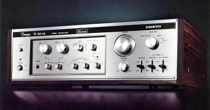
ONKYO Integra P-855NII
¥ 95,000 (released in 1975)
Commentary
In addition to further improving the transient response measures and dynamic characteristics of the equalizer circuit and tone circuit developed in the Integra Series, a fundamental study was also made on graining and sense of orientation in the middle and low frequency range to raise the quality of the preamplifier.
A dual-channel system independent power supply is used to supply power to the left and right channels independently.
This eliminates interchannel interference within the preamp and improves separation.
The power supply section uses a feedback stabilized ± 2 power supply type constant voltage circuit with a fluctuation rate of 1.7%, so that the effect of power supply fluctuation does not appear in the circuit that performs delicate voltage amplification.
For the equalizer amplifier circuit, the transient response characteristics are improved by using an operational amplifier type circuit with a single 4-chip configuration of differential 1-stage and final stage single, which was derived from detailed theoretical analysis of NF circuit.
For the tone amplifier circuit, we have adopted an operational amplifier circuit with a differential 1-stage 3-chip configuration determined by circuit analysis using a computer. We have taken various measures such as selection of the optimum time constant, securing of dynamic range in open loop, and improvement of SN ratio.
In the past, various elements such as the NF circuit were used to change the important rise characteristics in the middle and low frequency range, but this has been improved to realize a circuit with a good rise regardless of tone ON / OFF.
A transient killer circuit using a lead relay is employed to prevent a click when the switch is turned ON or OFF.
As coupling capacitors, which have a significant effect on playback sound, we use film capacitors with non-inductive extended foil structure and ultra-low leakage special electrolytic capacitors.
The volume and tone are adjusted using a precision trimming attenuator volume with an interlocking error of ± 0.5 dB. The volume can be adjusted in 43 contacts (middle position is also possible), and the tone can be adjusted in ± 5 steps of 2 dB steps.
In order to monitor the input of the equalizer amplifier, it has a built-in peak monitor with LED so that the clip point of the equalizer input can be monitored.
There are two levels of loudness, Low only and Low & High.
.JPG)
.JPG)
Model Rating
| Type | Preamplifier |
| Input Sensitivity / Impedance | Phono1 : 1.2, 2.4, 4.8mV/100, 50, 30k Ω Phono2 : 1.2, 2.4, 4.8mV/50k Ω Tuner, AUX1, 2, Play : 100mV/50k Ω |
| Total harmonic distortion factor (1 kHz at 1 V output) | 0.01% |
| Cross modulation distortion factor | 0.05% or Less (SMPTE, at 1 v output, 70 hz : 7 khz = 4 : 1) |
| RIAA characteristics (Phono1, 2) | 30 Hz to 15 kHz ± 0.2 dB or less 20 Hz to 20 kHz ± 0.5 dB or less |
| Frequency characteristic (Tuner, AUX1, 2, Play) |
15 Hz ~ 70 kHz + 0 -0.5 dB 10 Hz ~ 100 kHz + 0 -1.0 dB |
| Phono maximum allowable input (2.4 mv, T. H. D. 0.1%) |
1kHz(R.M.S.) 10kHz(R.M.S.) |
| S/N (IHF-A network Input shunt) |
Phono1, 2 : 75 dB or more Tuner, AUX1, 2, Play : 90 dB or higher |
| Output Voltage / Impedance | Output (100k Ω load) : 1 V (rating), 10 V (maximum) / 600 Ω Rec Out (Phono) : 100 mV (Rating) / 12k Ω |
| Tone Control (2 db Step Type) | Treble : ± 10 dB at 10 kHz, F.S Hift 2 kHz Bass : ± 10 dB at 100 Hz, F.S Hift 400 Hz |
| Turnover frequency | Treble : 2 khz, 8 khz, Defeat Bass : 400 Hz, 125 Hz, Defeat |
| Loudness (volume -30dB position) | + 5 dB at 70 Hz, + 3 dB at 10 kHz |
| Filter | High-Cut : 5 kHz, 20 kHz, 6dB/oct. Low-Cut : 50 Hz, 10 Hz, 12dB/oct. |
| Muting | -10dB, -20dB |
| Input-output polarity | EQ-AMP : Inphase Tone + Buffer-Amp : in-phase |
| Transient killer operating time | When SW-ON : about 7 seconds When SW-OFF : Start from 0.5 seconds |
| Semiconductor used | Transistor : 37 Diode : 40 pcs LED : 1 |
| Pwer | 100 VAC, 50Hz/60Hz |
| AC Output | Switched : Route 3 Unswitched : 1 line Total of 4 systems : 1100 VA |