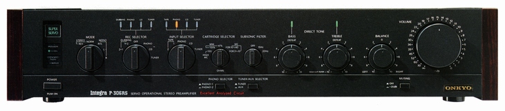
ONKYO Integra P-306R
¥ 110,000 (around 1983)
Commentary
Control amplifier using super turbo system.
Newly developed super turbo system is adopted.
This system combines a delta turbo circuit and a turbo filter circuit to suppress the modulation noise caused by the power transformer, expand the dynamic dynamic range by more than 20 dB, cut the harmonic noise caused by the flux generated by the transformer, and eliminate various electrical noise entering from the outside of the amplifier.
The delta turbo circuit is designed to prevent modulation noise caused by + - imbalance in the power supply when a low frequency signal of 100 Hz or less is input.
In the conventional power supply, only the positive and negative sides of the B power supply Chemi-Con and transformer windings, which supply power depending on whether the waveform of the signal flowing into the speaker is positive or negative, worked separately. Especially when the audio signal is 100 Hz or less, the power supply on one side, for example, the Chemi-Con on the negative side is off while the Chemi-Con on the positive side is being charged, and the charging current returns to the transformer through the midpoint. In the delta turbo circuit, the diode is turned off while the amplitude of the audio signal is small. Therefore, even while the positive side is being charged, the power supply flows into the Chemi-Con on the negative side without passing through the midpoint. As a result, the Chemi-Con on the negative side is charged up. Even if the voltage on the positive side drops due to the supply of power to the speaker, the voltage on the negative side rises reversely and the voltage fluctuation with respect to the voltage across the transformer is relatively small. This reduces the amplitude modulation of the charging current and suppresses the generation of modulation noise.
In addition, in this circuit, the diodes are delta-connected, so that the modulation noise does not flow only to the ground point of the circuit, even if the diode is turned on during high-power operation.
The turbo filter circuit is designed to prevent the modulation noise generated by the magnitude of the signal regardless of the frequency of the signal. The function of the circuit is to limit the harmonic spectrum generated by the pulse waveform supplied from the power transformer to only the amount necessary for the Chemi-Con charging.
There are two types of modulation noise generated by the harmonic spectrum. One type flows into the amplifier through the power supply line, and the other type flows out into the amplifier as magnetic flux from the power transformer. Especially in the micro-level amplification system in the amplifier, the noise voltage induced by this flux is generated, and it stains the original music signal. Furthermore, since this flux varies in proportion to the signal magnitude, it appears as signal information in the sense of hearing, and it has been considered to be the limit of the resolution of reproduced sound. In the turbo filter circuit, the modulation noise component is suppressed according to the turbo filter optimum attenuation characteristics, and the necessary charging energy is sent to the Chemicon.
This turbo filter circuit has a special CR filter placed in the power transformer. The inductance of this CR and transformer constitutes an equivalent circuit filter as shown below.
Another function of the turbo filter is to suppress modulation noise and prevent various types of noise from the external AC power supply from entering the power supply section, thereby reducing the difference in sound quality depending on the polarity of the AC power supply.
Super Servo Integral System is adopted.
This system focuses on sound quality problems caused by external factors such as the sound pressure directly received from the speaker and compatibility with the power amplifier. The system employs a super stabilizer, an output capacitor-less system, and a super servo cord to solve electrical and mechanical problems.
The super-stabilizer weighs about 3 kg and is reinforced as a chassis structure material, and vibration resistance is improved by weight. Furthermore, since each substrate is fixed to this stabilizer, vibration of the substrate itself is suppressed by the internal absorption effect.
In addition, various circuit currents flow inside the amplifier, and the resulting space charge is distributed in a complex manner on the insulator. These charges adversely affect the signal circuit during reconnection. The super stabilizer is made of a conductive layer made of special carbon particles, and space charge is equalized and partial reconnection is reduced, so that a higher purity sound can be obtained.
A common preamplifier has an output capacitor at the output end. However, the low frequency band was cut by the capacitor itself and the RC circuit using the input impedance and the output capacitor when connected to a power amplifier. This was a major problem especially when connected to a power amplifier with low input impedance or when multiple power amplifiers were driven in parallel.
In the Super Servo Integral system, since the output capacitor is eliminated, the low-frequency time constant is determined only by the servo circuit. Therefore, flat low-frequency characteristics can be obtained even when driving with a low impedance load, and at the same time, excellent distortion characteristics are realized.
By using the supplied super servo cord, the problem caused by the cable between the pre-power and the power is solved.
The positive input terminal of the output amplifier detects and suppresses harmful ultra-low frequency components that cause intermodulation distortion. The negative servo amplifier cancels components caused by the resistance of the connection between the P-306RS and the cable, the resistance of the cable itself, and the inductance of the cable itself, thereby preventing interference between channels and degradation of separation.
In addition, in order to eliminate the influence of diode characteristics due to contact at the pin plug part, a DC bias for idling is superimposed on the ground line to suppress non-linear characteristics and reduce IM.
The servo circuit operates when the ground line is connected, and its operation can be confirmed by the Connection lamp. The effect of this servo code can be effectively combined with any general power amplifier.
The equalizer amplifier has a simple one stage configuration that can handle MM to MC types. In the differential amplifier section at the front stage, two ultra-low-noise High Gm FETs are thermally coupled in a special metal case to improve thermal balance and suppress extraneous noise components. In addition, the differential section is para-connected in order to improve the overall S/N ratio by reducing the impedance of the signal system. In addition, in order to obtain wider frequency characteristics, the differential section is leased by cord connection to suppress the mirror feedback capacitance.
The second stage differential amplifier and the third stage differential amplifier with current mirror ensure large bare gain, and the partial feedback by skillful pole setting realizes high gain, excellent stability and low distortion factor.
The final stage is an A-class push-pull circuit, which smoothly transmits signals to the next stage amplifier at a low distortion rate even under heavy load in the high frequency range.
In addition to suppressing the interference between the left and right channels, the entire power supply system is designed to be low impedance to prevent the interference caused by the power supply between the front and rear stages, thereby suppressing the occurrence of dynamic modulation.
A high-speed response NF type constant voltage stabilizing circuit is used, and each circuit block is directly connected by a bus line to suppress distortion caused by interference.
Onkyo's unique direct tone method is used for tone control.
In this system, no tone amplifier is used and only passive elements are used to simplify the circuit. In addition, no capacitor is used in the signal circuit, which is problematic in sound quality.
Equipped with a cartridge selector for the MC cartridge to maximize the performance of the cartridge. (10 ~ 40 Ω, 3 ~ 10 Ω)
Uses a selector with a CD position.
Output can be directly input in the CD position.
The recording selector is only required for recording. By feeding the source to the REC pin terminal, the effect on sound quality is minimized.
By adopting a mechanical structure using non-magnetic parts, the effect of harmful high-order harmonics is eliminated.
High-performance special sound quality improvement type resistor is adopted.
.jpg)
.jpg)
.jpg)
.jpg)
.jpg)
.jpg)
.jpg)
Model Rating
| Type | Control amplifier |
| Input Sensitivity / Impedance | Phono MC : 130 μ V/100 Ω, 200 Ω Phono High MC : 2.5mV/100 Ω Phono MM : 2.5mV/47k Ω, 100k Ω CD, Tuner, Aux, Tape play : 150mV/47k Ω |
| Output Level / Impedance | Tape rec : 150mV/560 Ω Output : 1 V, 20 V (maximum) / 220 Ω |
| Phono maximum allowable input (THD 0.05%) | MC : 17 mv (1 kHz), 82 mv (10 kHz) MM, High MC : 300 mv (1 khz), 1400 mv (10 khz) |
| Frequency characteristic | Phono MC : 4 hz to 150 khz + 0. 2-3 db Phono MM : 1.8 Hz to 170 kHz + 0.2 -3dB CD, Tuner, Aux, Tape : 0.8 Hz to 170 kHz + 0 to 3 dB |
| Total Harmonic Distortion (20 Hz to 20 kHz, Vol-30dB, Output Voltage 3 V) | Phono MC : not more than 0.008% Phono MM : not more than 0.002% CD, Tuner, Aux, Tape : 0.0015% or less |
| Intermodulation distortion factor (at rated output, SMPTE method (70 Hz : 7 kHz = 4 : 1)) | Not more than 0.003% |
| S/N ratio (IHF network, input short) | Phono MC:69dB Phono MM:86dB CD, Tuner, Aux, Tape : 100 dB |
| Tone Control (Vol-20dB) | Bass : ± 8 dB (70 Hz) Treble : ± 8 dB (20 kHz) |
| Filter characteristic | High cut : 7 kHz, 6dB/oct. Subsonic cut : 15Hz/20Hz, 6dB/oct |
| Muting | -20dB |
| Transient killer operating time | Power on:7sec Power off:100msec |
| Pwer | 100 VAC, 50Hz/60Hz |
| AC outlet | Up to 1000W total Power switch interlock : 2 systems Power switch not linked : 1 system |
| Power consumption | 26W (Electrical Appliance and Material Control Law) |
| External dimensions | Width 480x Height 100x Depth 403 mm |
| Weight | 10.5kg |
.jpg)
.jpg)
.jpg)