ONKYO Integra M-506R
¥ 188,000 (around 1983)
Commentary
Stereo power amplifier using super turbo system.
Newly developed super turbo system is adopted.
This system combines a delta turbo circuit and a turbo filter circuit to suppress the modulation noise caused by the power transformer, expand the dynamic dynamic range by more than 20 dB, cut the harmonic noise caused by the flux generated by the transformer, and eliminate various electrical noise entering from the outside of the amplifier.
The delta turbo circuit is designed to prevent modulation noise caused by + - imbalance in the power supply when a low frequency signal of 100 Hz or less is input.
In the conventional power supply, only the positive and negative sides of the B power supply Chemi-Con and transformer windings, which supply power depending on whether the waveform of the signal flowing into the speaker is positive or negative, worked separately. Especially when the audio signal is 100 Hz or less, the power supply on one side, for example, the Chemi-Con on the negative side is off while the Chemi-Con on the positive side is being charged, and the charging current returns to the transformer through the midpoint. In the delta turbo circuit, the diode is turned off while the amplitude of the audio signal is small. Therefore, even while the positive side is being charged, the power supply flows into the Chemi-Con on the negative side without passing through the midpoint. As a result, the Chemi-Con on the negative side is charged up. Even if the voltage on the positive side drops due to the supply of power to the speaker, the voltage on the negative side rises reversely and the voltage fluctuation with respect to the voltage across the transformer is relatively small. This reduces the amplitude modulation of the charging current and suppresses the generation of modulation noise.
In addition, in this circuit, the diodes are delta-connected, so that the modulation noise does not flow only to the ground point of the circuit, even if the diode is turned on during high-power operation.
The turbo filter circuit is designed to prevent the modulation noise generated by the magnitude of the signal regardless of the frequency of the signal. The function of the circuit is to limit the harmonic spectrum generated by the pulse waveform supplied from the power transformer to only the amount necessary for the Chemi-Con charging.
There are two types of modulation noise generated by the harmonic spectrum. One type flows into the amplifier through the power supply line, and the other type flows out into the amplifier as magnetic flux from the power transformer. Especially in the micro-level amplification system in the amplifier, the noise voltage induced by this flux is generated, and it stains the original music signal. Furthermore, since this flux varies in proportion to the signal magnitude, it appears as signal information in the sense of hearing, and it has been considered to be the limit of the resolution of reproduced sound. In the turbo filter circuit, the modulation noise component is suppressed according to the turbo filter optimum attenuation characteristics, and the necessary charging energy is sent to the Chemicon.
This turbo filter circuit has a special CR filter placed in the power transformer. The inductance of this CR and transformer constitutes an equivalent circuit filter as shown below.
Another function of the turbo filter is to suppress modulation noise and prevent various types of noise from the external AC power supply from entering the power supply section, thereby reducing the difference in sound quality depending on the polarity of the AC power supply.
Super Servo Integral System is adopted.
The microphone effect occurs when the voice coil of the speaker vibrates. This electromotive force is always generated as long as the coil vibrates in a magnetic field. It cannot be fundamentally cancelled. In addition, this electromotive force affects the playback sound when the input signal of the speaker collides with this electromotive force. Especially in stereo sound fields, the sound reproduced from the R channel travels through the air and reaches the L channel speaker. With this sound pressure, the diaphragm of the L channel speaker vibrates. Moreover, there is a time lag for the sound to propagate between the two speakers. When an electromotive force different from the input signal that is generated enters the power stage, if the linearity of the power stage is not good, time difference distortion occurs between the input signal of the L channel and the input signal of the power stage, and this has a large effect on the playback sound.
In the Super Servo Integral Method, the generation of intermodulation distortion caused by this electromotive force is reduced to less than 1/10 (-20dB or more). The time difference distortion is not a problem as long as the linearity of the current amplification stage including the power stage is ensured. Therefore, in the conventional amplifier, NF is applied to correct the non-linear part of the current amplification stage, and the part which cannot be corrected by NF is corrected by the W super servo of the + side servo for ultra-low frequency and the - side servo for the ground line, so that it has some effect. In the Super Servo Integral Method, this idea is further advanced, the characteristics of the current amplification stage are greatly improved, and on top of that, the same correction as in the past is carried out to improve the time difference distortion.
Specifically, we apply positive and negative feedback by a linearity correction circuit only to the current amplifier stage from the output stage outlet, and improve the linearity of this stage to suppress time difference distortion.
Onkyo's original linear switching system is adopted.
The linear switching method is a B-class circuit with a fixed bias, but it was developed with the aim of being equal to the A-class circuit in terms of sound quality. It has a simple circuit configuration using simple circuit elements, but the crossover distortion is kept low and there is no change in sound quality due to bias fluctuations.
In addition, the use of high-fT power transistors keeps switching distortion within a negligible range.
Two large twin-winded power transformers are used for the power supply section, and a multi-tab type low-impedance, wide-range condenser is used as a low-inductance circuit directly connected to a bus earth for the rectifier capacitor.
In addition, the power supply / distribution lines and ground lines of each section are designed to have low impedance.
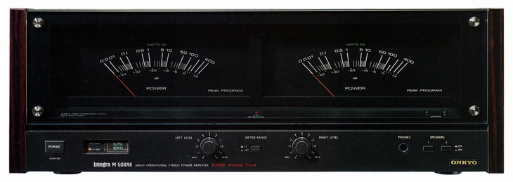
Equipped with a large peak meter.
Logarithmic compression and peak hold are performed by a monolithic IC with good stability, and there is almost no variation in left / right indication. In addition, to obtain high-speed response, it is driven by a dedicated meter drive circuit using an operational amplifier.
The level can be changed from 0 dB to 140W or 14W with the front switch.
Equipped with an auto-tracking bias system to ensure stable operation.
When there is a sudden change from a continuous large amplitude operation to a small amplitude operation with a music signal, the thermal gradient occurs due to the difference in heat capacity between the final blocks. In the case of a gradual temperature change, each part is affected in the same way, so there is no problem. However, in the case of a sudden change, the bias current value of the power section becomes unstable, which affects the reproduction of a low-level signal in particular.
The M-506RS has a 3-point sensing bias circuit at the output stage, detects the temperature difference between the three points of the pre-driver stage, driver section and power transistor, and controls the bias to achieve stable low distortion rate drive at all times.
The protection circuit uses a monolithic IC to increase reliability, and detects DC leakage voltage at the speaker terminals and power stage overcurrent. In the event of an emergency, the relay is instantly shut off to protect circuit components.
In addition, a highly reliable gold-plated silver contact relay is used for the speaker switching relay to prevent damping degradation by using parallel connection.
In addition, it is equipped with a low-pass filter for LR independent DC voltage detection that works even when the left and right polarities are different.
.jpg)
.jpg)
.jpg)
.jpg)
Model Rating
| Type | Stereo power amplifier |
| Amplifier Section (8 Ω Load, Both Channel Operation when No Display) | |
| Rated Output (20 Hz ~ 20 kHz) | 190W + 190W (4 Ω) 140W + 140W (8 Ω) |
| Total harmonic distortion rate (20 Hz to 20 kHz) | 0.003% or Less (at Rated Output) 0.0015% or Less (at 70W output) |
| Intermodulation distortion factor (at rated output, SMPTE method (70 Hz : 7 kHz = 4 : 1)) | Not more than 0.003% |
| Power Band Wiz (IHF-3dB, THD 0.2%) | 5 Hz to 100 kHz |
| Gain | 30dB |
| Frequency characteristic | 1 Hz ~ 100 kHz + 0 -1.5 dB |
| S/N ratio (IHF-A network, input short) | 120dB |
| Input Sensitivity / Impedance | 1V/47k Ω |
| Speaker load impedance | 4 Ω ~ 16 Ω |
| Damping factor (8 Ω, 1 kHz) | 180 |
| Output terminal | Speaker System1, 2 Headphones |
| Transient killer operating time | 5sec(Power on) 100msec(Power off) |
| Meter Section | |
| Range switching | x1 (140W), x0. 1 (14W) |
| Indication range | -40dB to + 4 dB |
| Indication accuracy | 0 ± 1 dB, -10 ± 2 dB, -20 ± 3 dB |
| Response speed | 100 usec (- ∞ - 0 dB) |
| Return speed | 1sec(0dB - -20dB) |
| <General> | |
| Pwer | 100 VAC, 50Hz/60Hz |
| AC outlet | Power switch not linked : 1 system, maximum 500W |
| Power consumption | 400W (Electrical Appliance and Material Control Law) |
| External dimensions | Width 480x Height 175x Depth 422 mm |
| Weight | 20.5kg |
.jpg)
.jpg)
.jpg)