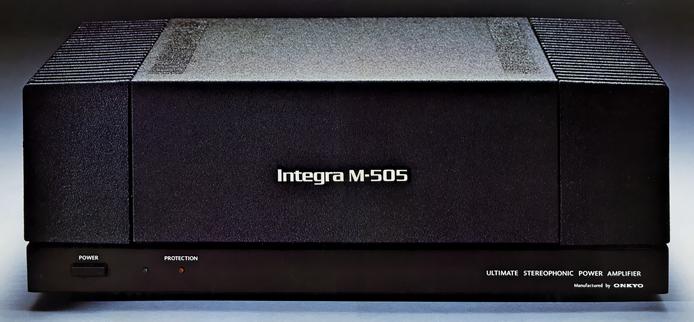
ONKYO Integra M-505
¥ 120,000 (around 1977)
Commentary
DC power amplifier with improved dynamic modulation (transient intermodulation distortion).
In order to improve dynamic modulation, D. L. C. (Dual Line Construction) direct-coupled power supply system is adopted to eliminate not only interference between left and right channels but also interference that occurs within the same channel.
For the power supply and distribution lines of each circuit, a multi-spray Bussler in held at ultra-low impedance is adopted, and extremely thick power distribution wires (cross-sectional area 5.5 mm) are used.2On the other hand, in the NF block of each stage, each branch is directly connected to the bus hotline for each point, and power is supplied to each stage individually. In addition, a 1 mm thick bus ground line is also used for the ground line, and dynamic modulation is prevented by making these supply and distribution lines low impedance.
The power supply unit is also designed to have low impedance. We have developed and used a high-capacity (18,000 μ Fx4) electrolytic capacitor that maintains low impedance up to 100 kHz. This capacitor was developed especially for audio applications. It has a distortion factor of -150dB at the third harmonic level at 10 kHz, an equivalent series resistance (E. S. R.) of 0.01 Ω or less, and a loss of tan δ of 0.25 or less. It achieves low impedance.
The D. L. C. system is used to reduce interference between the left and right channels by using a two channel D. L. C. system with a mono-amplifier that is independent of all circuits.
The power transformer with a large laminated core maintains regulation of 160W + 160W at 4 Ω output, and the stored energy in the power supply reaches 148 joules.
A new low-noise monolithic dual FET is used for the first stage differential amplifier to form a complete DC amplifier.
This newly developed FET consists of two FETs on a single pellet. The temperature characteristics and other characteristics are almost exactly the same, and the temperature difference is small because the pellet is the same. This FET is an ideal device for a DC amplifier. As a result, the temperature drift is stable within ± 20 mv at ± 30 ℃ for a temperature of 20 ℃. In addition, since this FET uses a ceramic base, it is more moisture-resistant than a conventional dual-in-line plastic package.
The first stage FET differential amplifier is an active broad of a constant current circuit with good temperature characteristics. It is designed to have a good common-mode rejection ratio. In addition, the low input impedance of the cascade connected transistor prevents the degradation of high frequency characteristics due to the feedback capacitance mirror effect.
In addition, impedance conversion is performed by placing an emitter follower next, and the frequency characteristic at the first stage is extended to 2 MHz.
The power stage is a pure complimentary service circuit using an NPN-PNP transistor with the same characteristics. The 3-stage Darlington connection reduces the load on the current mirror circuit of the drive stage and reduces distortion. The final stage achieves low distortion by using a TO-3 transistor with sufficient power in parallel push-pull and using it in a region with good linearity.
The drive stage employs a current mirror circuit using a high-voltage transistor with low junction capacitance and high fT. This reduces distortion and makes it less susceptible to power supply voltage fluctuations.
A large aluminum die-cast heat sink is used for the heat radiation part.
It is equipped with a protective circuit that electronically detects the output DC voltage and the power transistor overcurrent. If there is a problem, a relay disconnects the speaker. This circuit is also in standby mode when the power is turned on and can be seen by an indicator on the front panel.
Since DC may come in from the input other than when the amplifier has failed, the DC detection section is independent on the left and right sides and operates even when the DC polarity is different on the left and right sides. The overcurrent detection circuit quickly disconnects the speaker when the load is short-circuited or when the impedance is low.
The power transformer incorporates a high-precision temperature switch and a thermal fuse in each of the left and right sides. In the event of an abnormal temperature rise due to overload or failure, the power is turned off and the speaker relay is turned off. When the transformer cools down to normal temperature, they automatically recover and the thermal fuse does not blow during normal operation.
The switch on the rear panel allows you to switch the lower cutoff frequency from DC to 0.15 Hz to 10 Hz.
In the DC position, there is no capacitor in the signal path or NF loop from input to output, and it is a complete DC amplifier. In the 0.15 Hz position, it can be connected to a preamp with a DC leak, which cannot be connected to a DC amplifier. The coupling capacitor used for this is a low-distortion, low-loss special chemical capacitor selected by hearing with a particular emphasis on sound quality, so its performance in the audible band hardly changes.
The 10 Hz position is used as a subsonic filter to prevent the cone paper from swaying during disc playback.
Left and right independent level volume is mounted on the rear panel.
.JPG)
.JPG)
.JPG)
.JPG)
Model Rating
| Type | Stereo power amplifier |
| Rated Output (20 Hz to 20 kHz, Both Channel Drive) | 160W + 160W (4 Ω) 105W + 105W (8 Ω) |
| Dynamic Power | 160W + 160W (8 ω, 1 kHz) |
| Total harmonic distortion rate (20 Hz to 20 kHz) | 0.05% or Less (at Rated Output) 0.01% or Less (at 50W Output) 0.01% or Less (at 1W Output) |
| Intermodulation distortion factor (SMPTE70Hz : 7 khz = 4 : 1) | 0.01% or Less (at Rated Output) |
| Power Band Wiz (IHF-3dB, THD 0.2%) | 5 Hz to 100 kHz |
| Frequency characteristic | DC ~ 150 khz + 0 -1.5 db |
| Phase characteristic | DC ~ 100 kHz + 0 - 30 degrees or less |
| Filter characteristics | 0.15Hz/10Hz, -6dB/oct. |
| S/N ratio (IHF-A network, input shunt) | 110dB |
| Damping factor | 100 (8 Ω) |
| Load impedance | 4 Ω ~ 16 Ω |
| Input impedance | 100k Ω |
| Gain | 25.5dB |
| Rated input voltage | 1.5V |
| Semiconductor used | Transistor : 45 FET : 2 Diode : 31 Units |
| Pwer | 100 VAC, 50Hz/60Hz |
| Power consumption | 170W (Electrical Appliance and Material Control Law Standard) 430W maximum power consumption |
| External dimensions | Width 450x Height 165x Depth 322 mm |
| Weight | 17kg |