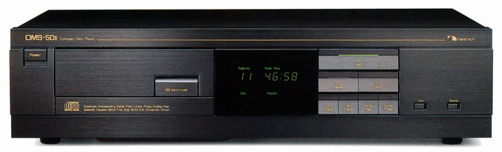
Nakamichi OMS-50II
¥ 208,000 (around 1986)
¥ 190,000 (around 1989)
Commentary
A CD player that suppresses glitches that occur during D/A conversion.
The cost performance of OMS-50II is improved by simplifying the OMS-70II by omitting the remote control and headphone output.
The newly developed glitch free D/A conversion system is used for the D/A conversion section, eliminating the sample-and-hold circuit.
The analog circuit of a typical CD player consists of a D/A converter followed by a sample-and-hold circuit followed by an analog low-pass filter. This sample-and-hold circuit mutes and removes the fine whisker-like digital noise called glitch, which is seen in the analog waveform output from the D/A converter, and samples and holds only the clean signal. However, the sample-and-hold circuit consists of analog switches, capacitors, and other components that are inferior in sound quality. Internal resistance of the switch itself, mixing of switching noise, and deterioration of sound quality due to capacitors occur.
In a glitch free D/A conversion system, a 16-bit digital signal, which is over-sampled by a digital filter by a factor of four, is first passed through a photocoupler to block the noise of the servo system. Next, data is converted into serial / parallel data, held in the state of parallel data, and each bit is output simultaneously with Lch and Rch. In order to prevent the occurrence of glitch, the D/A converter is strictly controlled by a digital griding circuit so that the switches of each bit operate simultaneously, so that the occurrence of glitch is close to 0.
As a result, the D/A converter achieves an excellent distortion factor of 0.0015% or less and eliminates the sample-and-hold circuit from the analog section.
The digital filter uses a 16-bit 4-times oversampling digital filter.
By over-sampling the 44.1 kHz PCM signal to 176.4 kHz, a factor of four, the lower limit of unwanted noise is reduced to 156.4 kHz. This makes it possible to use a third order linear phase Bessel filter with excellent phase and transient response characteristics.
The D/A converter uses a dual configuration 16-bit high-speed D/A converter with a built-in high-precision ladder resistor network made of a Nichrome thin film. It achieves high speed and high conversion accuracy by processing 16-bit digital signals that have been oversampled by a digital filter as they are.
An optical transmission system using a photo coupler is adopted after the digital filter to prevent digital noise from being transmitted through the ground loop.
For digital circuits, we are promoting the use of IC components to make the circuit smaller and reduce noise generation. For analog circuits, we have adopted a large circuit board and each circuit block is laid out loosely. In addition, the analog circuit board is sealed with an aluminum shield case to protect music signals from noise coming from the air.
In addition, three layers of pure copper bus bars for power supply are placed between the D/A converter and the analog filter to provide a shielding effect.
The power supply section has separate transformer windings for analog circuits (after the photocoupler) and digital circuits (servo and logic control). The rectifier circuit is also separated. A line filter is inserted into the power supply line of the digital circuit to prevent noise from mixing into the analog circuit due to the capacitance between windings inside the transformer.
In addition, as a countermeasure for analog circuits, the power supply consists of two stages. First, a master power regulator is used for the analog section winding, and then an independent local power regulator is used for each stage of the L/R channel to further stabilize the voltage. In addition, the local power regulator and master power regulator are non-NFB power supplies with no feedback loop. This is related to the low NFB of power amplifiers, and reduces the influence of voltage fluctuations between stages. For stages other than analog filters, local power regulators are also used in relay circuits and other circuits.
Each regulator does not use an IC, but uses a discrete configuration of transistors, and is designed with an emphasis on the grade of power supply as much as signal system.
It uses an opposed ground system, and the earth line is designed with sufficient consideration.
In a general circuit, the current of each stage flows from plus to ground and from ground to minus. However, when various currents from each stage flow into the signal ground, the reference ground potential fluctuates, and the effect of the flutter affects each stage, damaging the stereo image and making the sound muddy.
In the OMS-70II, an FET buffer is incorporated in the power supply line so that the current flows from plus to minus. The ground is designed to function only to regulate the reference potential. This prevents noise or contamination from entering the current, and therefore the DC stability of the power supply is improved. In addition, the Zener diode, which has less influence on sound quality, is used instead of the DC coupling capacitor as the stabilizing power supply.
For the analog filter, a third active type linear phase Bessel filter with a cutoff frequency of 30 khz is used discretely.
The Bessel filter consists of a two stage DC amplifier. The bare characteristics of the amplifier are enhanced as much as possible. As a result, a low distortion rate of 0.0003% can be achieved by applying only a small amount of NFB. The left and right channels are perfectly symmetrical, and the front and back of each channel are powered by independent regulators, reducing interference between the channels.
High-grade audio-only parts carefully selected through audibility tests, such as metal film resistors, mica capacitors, Cerafine capacitors, and completely non-inductive capacitors, are used, and brass cap type resistors for NFB are used.
The input section of each stage is a differential input by Hi-gm dual FET, and the gold plated pin jack is directly attached to the analog circuit board to prevent deterioration of sound quality caused by wiring.
The pickup section uses a 3-beam / astigmatic laser pickup with enhanced information pick-up capability of the central main beam, taking care to obtain more accurate information from the disc before relying on error correction.
The servo circuit also employs a newly developed digital signal processing LSI. This LSI has a built-in mechanism that performs focus and hold until the RF signal from the laser pickup passes through the scratch when the RF signal from the laser pickup drops out due to a scratch at the time of disk manufacturing. This LSI prevents sound skipping and sticking caused by the scratch.
Multiple LSIs for signal processing use a master clock system that synchronizes with a single crystal to prevent beat noise due to interference between clocks.
In order to suppress the effects of internal resonance and external vibration, we have devised disk chucking.
First of all, the disk drive mechanism is attached directly to the zinc alloy die-cast chassis to increase its rigidity and is independent of the main base chassis and disk loading mechanism. Moreover, the disk drive mechanism is completely floated from the main base chassis by means of spring and damping material so that it is less susceptible to internal resonance and external vibration.
In addition, the chucking arm that holds the disk employs a magnet chuck system. When the disk is mounted, the permanent magnet securely fixes the disk so that the arm completely separates from the disk, preventing transmission of chassis vibration to the disk. In addition, the unique centering mechanism prevents read errors due to disk eccentricity.
Equipped with time / total time / remaining time display function.
When a disc is loaded, the total number of tracks and total playing time are displayed for approximately five seconds. In normal regenerating condition, the time counter display can be switched between three types : Time, Total Time, and Time Remaining.
On OMS-70II, these three types of displays are also available for programs stored in memory during memory playback.
FL tube is used for the display part.
Uses gold-plated output terminal.
It is equipped with functions such as skip search, double speed queuing, repeat play, and direct operation.
The system remote terminal is mounted, and when the control amplifier CA-70 is connected, it can be operated by the wireless remote control included with the CA-70.
.jpg)
.jpg)
Model Rating
| Type | CD Player |
| Reading system | Non-contact optical (semiconductor laser used) |
| Error correction method | CIRC method |
| Number of channels | 2-channel stereo |
| Sampling frequency | 44.1kHz |
| Quantization | 16-bit straight line |
| Disk rotational speed | Approx. 200 ~ 500 rpm (Constant Linear Velocity) |
| Wow and flutter | Below the measurement limit |
| Frequency characteristic | 5 Hz to 20 kHz ± 0.5 dB |
| Signal-to-noise ratio | 104 dB or more (IHF A-WTD) |
| Dynamic range | 96 dB or more |
| Total harmonic distortion factor | 0.0025%(1kHz) |
| Total harmonic distortion factor + noise | 0.0035%(1kHz) |
| Channel separation | 100 dB or more |
| Output | Line : 2V/100 Ω (1 kHz, 0 dB) Headset : 35 mW or more, 40 ohm load (1 kHz, 0 dB) |
| Pwer | 100 VAC, 50Hz/60Hz |
| Power consumption | 25W max. |
| External dimensions | Width 435x Height 100x Depth 308 mm |
| Weight | Approx. 7.3 kg |
.jpg)