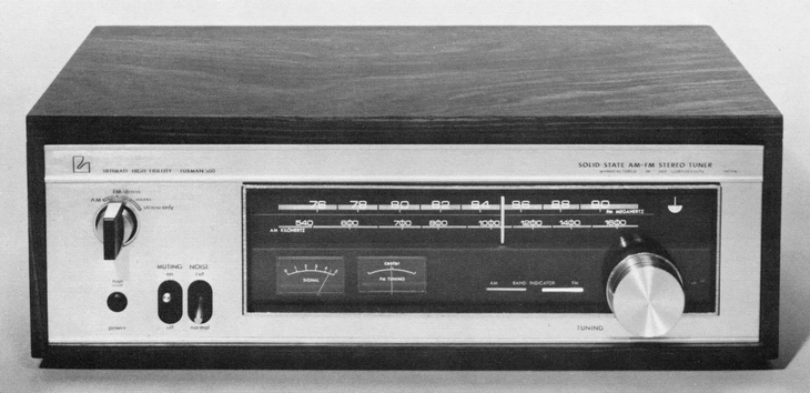
LUXMAN WL500
¥ 69,500 (released in December 1971)
Commentary
An FM/AM tuner developed to match the SQ500X series.
The FM tuner uses a dual-gate MOS-type FET for the front-end high-frequency amplifier circuit and frequency conversion circuit to enhance sensitivity, cross-modulation characteristics, and stability against excessive input in strong electric fields.
In addition, the use of 4-row variable capacitor ensures sufficient selectivity.
The intermediate frequency amplifier circuit combines three ICs and a block filter to improve various characteristics.
The block filter has a selectivity comparable to that of the crystal filter and has excellent phase characteristics, so it is effective in reducing distortion.
The multiplex circuit uses a switching method.
This circuit improves the separation characteristics by adding a cross-talk cancellation circuit that cancels out the components that leak into the reverse channel from the left and right signals separated in advance. In addition, a low-pass filter that cuts out the frequency components of 16 kHz or higher is added to almost eliminate carrier leakage.
The AM tuner section consists of one stage of high frequency amplification and two stages of intermediate frequency amplification to ensure sufficient stability.
The intermediate frequency amplifier stage is combined with a wide-band transformer to obtain good sound quality, and the strong AGC suppresses distortion in the high-field region.
A 2-meter system is adopted, and the signal strength meter and the center tuning meter are configured independently.
It is equipped with a pure electronic muting circuit to eliminate unpleasant inter-station noise.
A high-blend noise filter is used to eliminate high-frequency noise during FM stereo broadcast transmission.
Many of the multi-path detection signals used for oscilloscope vertical signals are of low power, but WL500 is designed to amplify this signal to provide sufficient output, so that most oscilloscopes can be used for multi-path observation.
The power supply section uses a constant voltage power supply circuit.
.jpg)
Model Rating
| Type | FM/AM Tuner |
| FM Tuner Section | |
| Receiving frequency | 76 MHz to 90 MHz |
| Practical sensitivity of IHF | 1.7 μ V |
| Image ratio | 85dB(83MHz) |
| IF interference rejection ratio | 90dB(83MHz) |
| Capture ratio | 1.5dB(1mV) |
| Two signal selectivity | 70 dB (± 400 kHz) |
| Amplitude modulation suppression | 53dB(1mV) |
| Signal-to-noise ratio | 70 dB or more |
| Frequency characteristic | 20 Hz to 15 kHz |
| Stereo separation | 40dB(400Hz) |
| Carrier leak | -65dB or more |
| Total harmonic distortion factor | Stereo : not more than 0.5% Mono : not more than 0.2% |
| Antenna impedance | 300 Ω (balanced) 75 Ω (unbalanced) |
| <AM Tuner Section> | |
| Receiving frequency | 525 kHz to 1605 kHz |
| Practical sensitivity of IHF | 320 μ V/m (built-in antenna) |
| Image ratio | 80dB(1000kHz) |
| IF interference rejection ratio | 75dB(1000kHz) |
| Signal-to-noise ratio | 48 dB or more |
| Frequency characteristic | 40 Hz to 5 kHz |
| <General> | |
| Output voltage | FM : 1.7 V (100% modulation) AM : 0.4 V (30% modulation) |
| Output impedance | FM : 400 Ω |
| Attachment | Muting Switch (FM/AM) High-frequency noise filter (FM stereo) Output Level Control (FM/AM) Antenna Attenuator (FM) Multipath Detection Terminal (FM) Coaxial Connector (FM) |
| Semiconductor used | MOS Type FETx2 Transistor x33 pcs ICx3 pcs Diode x24 pcs |
| External dimensions | Width 450x Height 160x Depth 268 mm |
| Weight | 7.8kg |