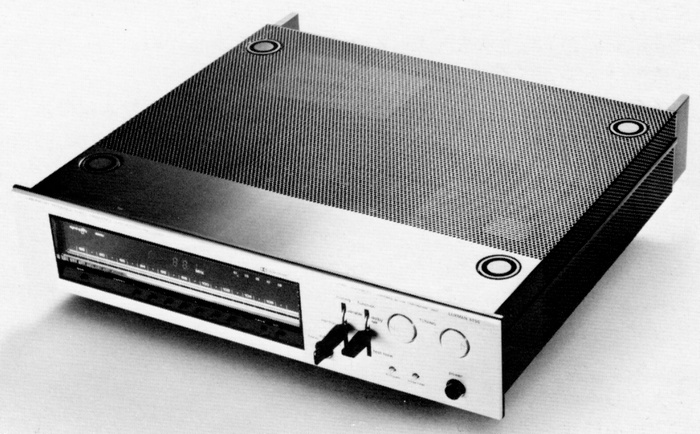
LUXMAN 5T50
¥ 220,000 (released in June 1977)
Commentary
Laboratory Reference Series digital synthesizer FM stereo tuner.
In the digital synthesizer method, the oscillator circuit, which can be called the heart of the tuner, is composed of a frequency synthesizer controlled by a phase locked loop (PLL), and the number of visits is determined directly by digital code.
As a result, we have achieved tuning accuracy and frequency stability that cannot be compared with conventional analog tuners.
The front end uses MOS-type FETs for the high-frequency amplifier stage and mixer stage, and a buffer circuit is provided after the low-distortion local oscillator circuit to improve the interference removal characteristics.
In the intermediate frequency amplifier stage, two sets of 4-pole block filters with special emphasis on phase characteristics and ceramic filters are combined to achieve both high selectivity and low distortion by taking advantage of the advantages of both filters. In addition, a quadrature broadband detection circuit that is resistant to overmodulation also contributes to low distortion.
The multiplex circuit employs a low-distortion PLL IC and is designed to provide excellent separation characteristics.
A full-scale constant voltage power supply circuit is used for the power supply part.
Built-in memory tuning function.
The 5T50 uses a C-MOS IC memory element and employs a purely electronic memory circuit that is stored in a digital code. It can store and erase desired stations. There are seven stations that can be stored in memory. Stored stations are not erased even when the power is turned off.
Auto tuning moves automatically when the tuning key is pressed in the UP or DOWN direction until the next station is located, and stops when the radio wave is caught.
In manual tuning, if you lightly touch the UP or DOWN tuning key, the receiving frequency will change up or down in increments of 100 kHz. If you press and hold the tuning key, the receiving frequency will change at the preset speed. If you release the key, tuning will stop.
It is equipped with functions such as a signal quality indicator that displays the reception status of the broadcasting station as a number from 0 to 5, a test tone oscillation circuit that determines the recording level of the tape deck, a multipath detection circuit, muting level adjustment function, scanning speed adjustment, output level adjustment, etc.
An LED dial scale is installed so that the dial scale can be judged intuitively by taking into account the operation sense of the analog tuner. This system is equipped with 14 LEDs that display the FM broadcasting band from 76.1 MHz to 89.9 MHz every 1 MHz and 10 LEDs that display between 1 MHz every 100 kHz. The reception frequency can be judged by the double display of numbers and LEDs.
In the Laboratory Reference Series, in which legs are attached to the lower part and metal brackets are attached to the upper part, and these are supported by metal supports, so that when the product is stacked, an excessive load is not applied to the product lying below.
In addition, the legs and brackets fit together perfectly so that they do not slip or fall over.
As an optional part sold separately, there was a standard rack mounting bracket of EIA standard.
.jpg)
.jpg)
Model Rating
| Type | FM stereo tuner | ||
| Receiving frequency | 76.1 mhz to 89.9 mhz | ||
| Practical sensitivity | 1.7 μ V (300 Ω, IHF) / 9.8 dBf (new IHF) | ||
| SN ratio 50 dB quieting sensitivity | Mono : 3.2 μ V (IHF) / 15.2 dBf (new IHF) Stereo : 40 μ V (IHF) / 37.2 dBF (new IHF) |
||
| Two signal selectivity | 72 dB (100 μ V, ± 400 kHz) | ||
| Amplitude modulation suppression | 55dB | ||
| Capture ratio | 1.1dB | ||
| Image ratio | 100dB | ||
| IF interference rejection ratio | 100dB | ||
| Spurious characteristic | 100dB | ||
| Signal-to-noise ratio | 70dB | ||
| Frequency characteristic | 30 Hz ~ 15 kHz + 0.2 -1dB 50 Hz to 10 kHz ± 0.2 dB |
||
| Total harmonic distortion factor |
|
||
| Stereo separation | 48dB(100Hz) 50dB(1kHz) 48dB(10kHz) |
||
| Carrier leak | -65dB | ||
| Antenna impedance | 300 Ω (balanced) 75 Ω (unbalanced) |
||
| Output voltage | Fix:1V Variable : 0 to 1 V |
||
| Output impedance | 600 Ω | ||
| Attachment | Purely electronic memory tuning circuit Autotuning circuit Numeric signal quality indicator Recording calibrator Multipath detection circuit Muting level adjustment Scanning speed adjustment Antenna attenuator Output level adjustment |
||
| Power consumption | 30W | ||
| External dimensions | Width 442x Height 101x Depth 400 mm | ||
| Weight | 8.7kg |
.jpg)