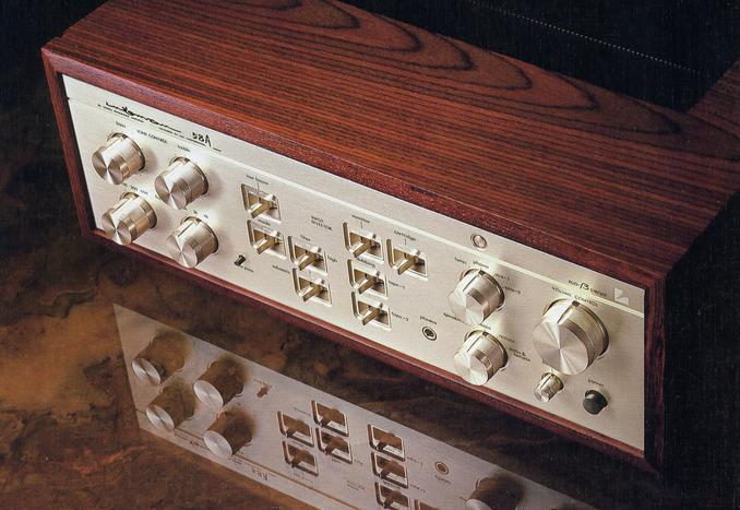
LUXMAN L-58A
¥ 149,000 (Released in September 1979)
Commentary
This is a pre-main amplifier with an original duo-beta circuit that not only improves the characteristics but also improves the quality of the amplifier to improve sound quality.
Duo Beta Circuit means a circuit that combines two NFBs.
This circuit does not attempt to improve various characteristics of the amplifier by investing a large amount of NFB. Instead, various characteristics are improved by creating an amplifier with good quality (bare characteristics) and combining it with a small amount of NFB and DC servo.
In the power amplifier section, a pure complimentary service differential push-pull circuit using FETs for N-channel 2SK163 and P-channel (2SJ44) is adopted at the input stage to improve bare strain characteristics as a DC-amplifier configuration.
In addition, everything from the input stage to the output stage is composed of a push-pull circuit, and at the same time, a transistor and FET with high ft (high cutoff frequency) and low Cob (collector output capacitance) are adopted to reduce distortion.
The output stage employs MOS FETs (2SK134 and 2SJ49) with an ft of approximately 500 MHz. In addition to allowing a bias current of 300 mA or more, a high-speed driver circuit is combined to create a "notchless class A" amplifier that does not perform switching operation.
In addition, the open-loop gain (bare gain) has been reduced and bare frequency characteristics have been improved by one order of magnitude through the use of an element with excellent high-frequency characteristics and a circuit device such as a local NFB.
As a result, the bare distortion factor of the power amplifier has been improved to 0.4% (from 2-5% in the conventional model) and the slew rate to 300 v / μ sec (from 10 v / μ sec in the conventional model).
The equalizer uses a cascode input bootstrap circuit with four FETs at the input stage, combined with a dynamic resistance circuit with transistors to reduce bare strain.
In addition, in order to keep the output impedance as low as possible, a SEPP circuit (single ended push-pull circuit) with four transistors is adopted to reduce bare strain.
As a result, the bare distortion factor of the preamplifier (equalizer stage) has been improved to 0.2% (previously 2-5%) and the slew rate to 150 V / μ sec (previously 10 V / μ sec).
At the Duo Beta Circuit, TIM distortion is reduced by applying NFB, which is reduced to less than one hundredth of that of conventional amplifiers, to the amplifier circuit with improved bare characteristics, thereby improving sound quality in the middle and high range.
The duo-beta circuit uses a unique DC servo circuit to prevent cross-modulation distortion and SN ratio degradation due to tight low-frequency playback, reduced damping factor caused by reduced NFB, cone excursion of speakers, etc.
This DC servo circuit is combined in parallel with a small-volume NFB circuit and uses a low-noise FET amplifier, so a high-quality film capacitor can be used for the filter circuit, enabling tight low-frequency reproduction.
In order to give priority to sound quality, the head amplifier for MC uses a DC amplifier configuration in which FETs are connected in parallel instead of connecting many input FETs.
N-channel FETs with excellent noise characteristics are connected in parallel, and a constant-current circuit is combined to create a DC amplifier configuration with particularly improved high-frequency characteristics. As a result, there is a slight disadvantage in the SN ratio. However, we have solved this problem by adopting an automatic gain adjustment method that automatically adjusts the amplification factor when the impedance of the connected MC cartridge changes.
A buffer amplifier is provided in front of the tone control circuit to prevent the tone control circuit from being affected by other circuits. This eliminates the flat amplifier that causes the sound quality degradation, and the power amplifier circuit covers the insufficient amplification.
For the buffer circuit and tone control circuit, a cascode-connected source follower circuit with FET input is used, and for the tone control circuit, LUX system NF type with bending point switching which is easy to change characteristic is adopted.
In addition, these circuits can be bypassed when tone control is not required.
In the power supply circuit of the power section, high-frequency characteristics have been improved by adopting a high-capacity block and condenser for sound quality and by combining a film condenser in parallel.
The constant voltage power supply for the preamplifier section employs a power transistor with a fast switching speed to sufficiently reduce the circuit impedance.
In addition, a constant voltage power supply is used for the pre-driver stage of the power amplifier section to stabilize operation.
In order to minimize interference between the metal chassis inside the amplifier and the wiring circuit, the chassis corresponding to the printed circuit board is hollowed out.
In addition, the cabinet is a wooden box made of real wood, and the shielding of the box is limited to the minimum necessary level, and ultra-thin aluminum foil is used to completely eliminate eddy current distortion.
.JPG)
.JPG)
.JPG)
Model Rating
| Type | Integrated amplifier |
| Continuous effective output | 100W + 100W (8 Ω, both channel operation, 20 Hz to 20 kHz) |
| Total harmonic distortion factor | 0.015% or Less (8 Ω, 100W, 20 Hz to 20 kHz) |
| Cross modulation distortion factor | 0.015% or Less (8 Ω, 100W, 60 hz : 7 khz = 4 : 1) |
| Frequency characteristic | Phono MM, MC-1 : 20 Hz to 20 kHz ± 0.2 dB Tuner, aux1, 2, main in : 10 Hz to 100 kHz -1dB |
| Input Sensitivity / Impedance | Phono MM : 1.5mV/50k Ω Phono MC-1 : 1.5mV/100 Ω (direct to equalizer) Phono MC-2 : 0.05mV/2 Ω ~ 0.15mV/40 Ω (Automatic gain adjustment type head amplifier operates) Tuner, aux1, 2 : 220mV/20k Ω Main in : 220mV/820k Ω |
| Signal-to-noise ratio (IHF-A Input short) |
Phono MM : 80 dB or more Phono MC-1 : 80 dB or more Tuner, aux1, 2, main in : 100 dB or more |
| Tone control | LUX System NF Type with Bending Point Frequency Switching Low-pass curve point : 150 Hz, 300 Hz, 600 Hz High-frequency bending point : 1.5 kHz, 3 kHz, 6 kHz |
| Output Level / Impedance | Pre out : 220mV/220 Ω |
| Attachment | Subsonic Filter (15 hz, off, 30 hz) High-Cut Filter (9 khz, 0 ff, 15 khz) Low Boost Switch (70 Hz, off, 150 Hz) Tape monitor switch Tape dubbing & rec off switch Speaker selector Headphone jack |
| AC outlet | Switched : Route 3, max300W Unswitched-1 line, max200W |
| Power supply voltage | 100 VAC, 50Hz/60Hz |
| Power consumption | 300W (Electrical Appliance and Material Control Law) |
| External dimensions | Width 466x Height 181x Depth 378 mm |
| Weight | 15.3kg |
.jpg)