DENON TU-500
¥ 89,800 (Released in November 1974)
Commentary
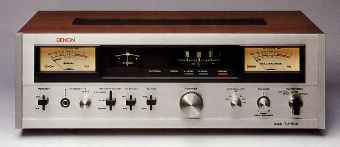
FM stereo tuner with drum type dial.
A 12 cm diameter drum is used for the dial part to reduce the area occupied by the panel and to read the received frequency accurately.
With this rotary drum type dial, the total travel length of the scale is 28.3 cm, approximately 1.5 times longer than that of conventional machines. Combined with the use of a frequency proportional type varicon, the scale achieves an easy-to-see equal spacing of 200 kHz.
The dial rotation mechanism uses oil-less, oil-containing polyacetal resin to keep the initial operability of the tuning knob for a long time.
The two meter type of signal meter and center type tuning meter is used for the tuning instruction. The large meter at the left end is also used as a signal meter and can read the input voltage of the antenna terminal.
In addition to the signal meter, the left meter operates as a level meter for the tuner output L-ch. The performance of this level meter conforms to the regulations of the broadcasting station class VU meter.
The large meter on the right is a null balance check meter in addition to the Rch level meter. Null balance is a function to ensure correct electrical balance when balance control a stereo circuit.
The left and right level meters also function as independent measuring instruments.
The input impedance is as high as 200k Ω or more, and by switching the external ATT on the front, the steady state audio signal voltage from -30dB (24.5 mv) to + 33 db (34.6 v) can be measured.
When combined with an amplifier that does not have a level meter, it can be used as an output meter of the amplifier, and the meter on the right can be used as a null balance checker.
Equipped with a multi-path terminal, antenna selection and direction / height adjustment can be performed correctly.
The input terminal from the antenna is equipped with a special 75 Ω F-type connector for a coaxial feeder with less transmission loss and induction of neighbor noise. It is directly connected to the front end, giving consideration to the transmission characteristics of weak radio waves.
At the front end, a single tuning circuit of a series of varicon is passed through, and high frequency amplification of a single bi-gate MOS-FET is performed immediately to maintain high S/N against weak radio waves. After that, a triple tuning circuit using three series of varicon is added, and mixed amplification with local oscillation frequency is performed by the bi-gate MOS-FET. Thus, the structure is constructed so that even strong radio waves are not distorted and do not cause blocking phenomenon with appropriate gain setting.
A modified clap-type oscillation circuit is used for the local oscillation circuit. This circuit is a common-collector type. The operation of the transistor is hardly affected by power supply voltage fluctuation and temperature change, and the output is directly extracted from a resonant circuit with a clean waveform, so that harmonics are less.
We also use carefully selected temperature compensation capacitors, oscillation coils with excellent temperature and humidity resistance, and hand wiring to reduce stray capacitance. In addition, the oscillation frequency is stable because the oscillation output is injected into the second gate of the mixing double-gate FET.
In the IF section, two sets of three stage direct-coupled differential amplification ICs with ideal limiting (amplitude limiting) function are mainly used. In addition, transistors with a wide dynamic range are used to construct multistage amplification with good linearity.
The coupling and selection elements between them are ceramic 2-element type with high selectivity and use 4 sets of flat phase characteristic filters with emphasis on sound quality.
FM detection uses a ratio detection circuit for a wide band with low output impedance.
The MPX circuit is a stereo decoder IC integrated with PLL switching and pulse oscillation circuits.
Both the left and right channels are designed to reduce distortion by stacking two double-stage direct-coupled amplifier circuits for a total of four stages, and by using a newly developed 3-stage low-pass filter to cut unwanted pilot signal and subcarrier leakage.
There are two types of output terminal : fixed and variable.
In addition to Mono and Auto, the Function Selector also has a Stereo-only position. The stereo output is automatically sent out when stereo broadcast transmission, and automatically stops when it changes to Mono.
Equipped with a headphone jack with volume.
Equipped with a muting switch, noise between stations can be eliminated.
Equipped with a high blend switch, noise can be suppressed without losing frequency characteristics.
.jpg)
Model Rating
| Type | FM stereo tuner |
| FM Tuner Section | |
| Circuit system | Superheterodyne system |
| Receiving frequency range | 76 MHz to 90 MHz |
| Intermediate frequency | 10.7MHz |
| Practical sensitivity (IHF) | 1.7 μ V |
| Effective selectivity (IHF) | 80dB |
| Image interference ratio | 110dB(83MHz) |
| IF interference ratio | 110dB(83MHz) |
| Spurious response | 110dB(83MHz) |
| AM suppression ratio | 60dB(IHF) |
| Capture Ratio (IHF) | 1.0dB |
| Unwanted radiation | 50 μ V/m |
| <Audio section> | |
| Circuit system | Adoption of phase-locked loop type stereo demodulation circuit |
| 19 kHz & 38 kHz suppression ratio | 65dB |
| Frequency characteristic | 20 Hz ~ 15 kHz + 0.2 -1.5 dB (with 19 kHz Filter) |
| Signal-to-noise ratio | 75dB |
| Total harmonic distortion factor | Stereo : 0.2% (1 kHz at 90% modulation) 0.3% (50 Hz to 5 kHz at 90% Modulation) Mono : 0.2% at 1 kHz, 100% modulation 0.3% (50 Hz to 10 kHz at 90% Modulation) |
| Separation | 45dB(1kHz) 40 dB (100 Hz to 10 kHz) |
| Output voltage (at 100% modulation) | Fixed : 1 V Variable : 0 ~ 1.5 V |
| Output impedance | Fixed : 4.7k Ω Variable : 200 Ω |
| Remarks | Null balance possible |
| Headphone Amplifier Section | |
| Adaptive load impedance | 8 Ω |
| Rated output | 10mW(0.28Vrms) |
| Frequency characteristic | 50 Hz ~ 10 kHz + 0 -1.5 dB |
| Level Meter Section | |
| External signal measuring range | -20, -10, 0, + 10, + 20, + 30 dB (0 dB : 0.775 Vrms) |
| Same input impedance | 123k Ω |
| Indication error | Within ± 0.2 dB (each range, 1 kHz, near VU scale 0) |
| Frequency characteristic | 20 Hz to 15 kHz ± 0.5 dB |
| Dynamic characteristic | Conform to JIS C 1504 |
| <General> | |
| Antenna terminal | 75 Ω F-type connector 300 Ω / 74 Ω, Screw Type |
| Connection terminal | Multipath detection terminal Detection output terminal (output for 4 ch & SCA) Level meter external terminal Same path terminal |
| AC outlet | Unswitched : 250 Wmax, one train |
| Pwer | 100 VAC, 50Hz/60Hz |
| Power consumption | 25W |
| External dimensions | Width 430x Height 140x Depth 308 mm Width 430x Height 140x Depth 350 mm (listed in separate catalog) |
| Weight | 8.5kg 9 kg (listed in separate catalog) |
.jpg)
.jpg)