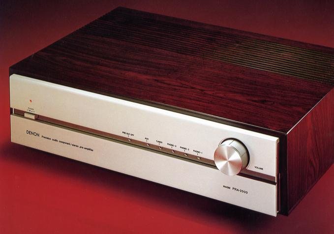
DENON PRA-2000
¥ 200,000 (released in 1979)
Commentary
A control amplifier equipped with a real-time equalizer amplifier that challenges the limits of disc playback.
The EQ section uses a non-feedback real-time equalizer amplifier, a further development of the CR type.
The configuration consists of two stages of DC linear amplifier with newly developed low-noise FET and CR-type equalizing filter between stages. The first stage FET is parallel differential, and a cascode boot-strap circuit is adopted to prevent degradation of high-frequency characteristics while greatly improving S/N.
In addition, the input-coupled capacitor has been removed, not only eliminating the sound coloring by the capacitor, but also Pc800mW ・ fTCombined with a 150 v high-voltage power supply operation using a 120 mhz high-power, high-speed transistor, it realizes a high power and wide dynamic range with a clipping level of 47 v.
In addition, high S/N has been achieved by reducing impedance of the CR-type equalizing filter.
The CR element uses a polypropylene capacitor and ± 1% metal film deposition resistance.
The Phono3 terminal is directly connected to the MC head amplifier composed of 22 transistors.
This head amplifier has the same circuit configuration as DENON's top-of-the-line head amplifier HA-1000. For example, a PNP type low-noise transistor, which is advantageous for low noise, is connected in parallel at the first stage.
In addition, in order to ensure performance as a dedicated MC head amplifier, a ± 15 v stabilized power supply with a booster for increasing the power supply is provided inside the head amplifier board to minimize the power supply impedance and achieve high S/N and high speed.
The flat amplifier section uses a 10k Ω low-impedance volume circuit.
As a result, the S/N degradation due to high-resistance thermal noise and the mirror effect due to transistors have been combined to eliminate the disadvantages of high-impedance volume such as increased distortion, formation of high-cut filters due to high machining and stray capacitance of wires, and deterioration of slew rate and rise time.
In addition, a direct DC servo system is adopted. The parallel configuration of the first stage FET differential amplifier and the servo feedback circuit that replaces the servo amplifier are used to achieve low distortion and high S/N and to eliminate the output coupling capacitor.
Each selector switch is a soft push type with an electronic circuit that switches with a light touch in consideration of operability.
The lead relay, which does not change over time, is placed in a position that is not affected by the routing of the audio signal wiring so as to give consideration to sound quality.
In addition, it is equipped with compound functions such as a one shot muting mechanism in which a one shot trigger circuit is activated when switching and the power to the output side is temporarily turned off.
The power supply section is equipped with a large 5-shield toroidal transformer with a winding diameter of 1.2 mm and a capacity of 50 VA. The transformer is resistant to fluctuations in the power supply and fully takes into account leakage flux.
In order to send high-quality sound without unnecessary coloring to the power amplifier, the signal from the disk is directly sent from the equalizer amplifier to the flat amplifier without passing through the buffer amplifier. The phono channels are directly connected to the flat amplifier, while the aux, tuner and tape channels are automatically connected to the buffer amplifier by function switching.
In addition, the buffer amplifier for impedance matching of Tuner and Tape and for subsonic filter is newly developed symmetrical complimentary service FET-DC configuration, which prevents the generation of second harmonic distortion, which is a problem, and obtains high S/N. In addition to preventing the generation of distortion due to the feedback capacitance between the inputs of the first stage FET, the cascode bootstrap circuit, which is also used for the equalizer amplifier, is adopted for high-voltage operation of 150 V.
The left and right channels of each part are arranged equally, and the signal unit and power supply are separated to prevent mutual interference.
In addition to the shield between the upper and lower boards of the amplifier section, the MC head amplifier and equalizer amplifier have a 2-stage structure using aluminum plates to maintain high S/N and prevent magnetic distortion.
Equipped with an emergency protector circuit that protects the elements of the power amplifier in the event of an error.
Uses carefully selected high-quality parts for audio such as Λ condenser.
Equipped with functions such as subsonic filter and 2-stage muting.
.JPG)
.JPG)
Model Rating
| Type | Control amplifier |
| <MC head amplifier section (Phono3 → rec out)> | |
| Input Sensitivity / Impedance | 0.125mV/100 Ω |
| Maximum allowable input | 19mV(1kHz) |
| Total harmonic distortion factor | 0.003% or Less (20 Hz to 20 kHz) |
| Frequency characteristic | 20 Hz to 100 kHz ± 0.2 dB |
| Signal-to-noise ratio (IHF-A) | 79dB |
| Input equivalent noise level | -157dBV |
| Separation | 70 dB or More (20 Hz to 20 kHz) |
| Gain (head amplifier only) | 26dB |
| Equalizer Amplifier Section (Phono1, 2 → rec out) | |
| Input Sensitivity / Impedance | 2.5mV/50k Ω Phono2 can be switched to 100 Ω |
| Maximum allowable input | 380mV(1kHz) |
| Maximum Output / Rated Output | 23V/150mV |
| Harmonic distortion factor | 0.002% or Less (20 Hz ~ 20 kHz, 4 V Output) |
| RIAA deviation | 20 Hz to 100 kHz ± 0.2 dB |
| Signal-to-noise ratio (IHF-A) | 86dB |
| Separation | 100 dB or More (20 Hz to 1 kHz) 90 dB or More (20 kHz) |
| Gain | 35.6dB(1kHz) |
| Preamplifier Section (AUX → Pre Out) | |
| Input Sensitivity / Impedance | Tuner, AUX, Tape1, 2 : 150mV/50k Ω |
| Maximum allowable input | 23V |
| Maximum Output / Rated Output | 25V/1.5V |
| Total harmonic distortion factor | 0.002% or Less (20 Hz ~ 20 kHz, 3 V Output) |
| Frequency characteristic | 10 Hz ~ 100 kHz + 0 -0.1 dB 10 Hz ~ 500 kHz + 0 -1dB |
| Signal-to-noise ratio (IHF-A) | 105 dB or more |
| Separation (20 Hz ~ 20 kHz) | 100 dB or more (Volume MAX) 80 dB or more (Volume -20dB) |
| Gain | 20dB |
| Muting | -20dB & ∞ |
| Subsonic filter | 16 Hz, 12dB/oct. |
| TIM distortion factor | Not more than 0.003% |
| IM distortion factor | Not more than 0.002% |
| <General> | |
| Semiconductor used | Transistor : 149 units FET : 14 IC : 1 Diode : 68 Pieces Rectifier stack : 3 pieces Lead Relay : 7 Relays : 2 LED : 6 pcs |
| AC outlet | Power switch interlock : 2 systems Power switch not linked : 1 system |
| Power supply voltage | 100 VAC, 50Hz/60Hz |
| Power consumption | 38W |
| External dimensions | Width 455x Height 132x Depth 357 mm |
| Weight | 10.5kg |
| Attachment | 1 x low-capacity connection code |