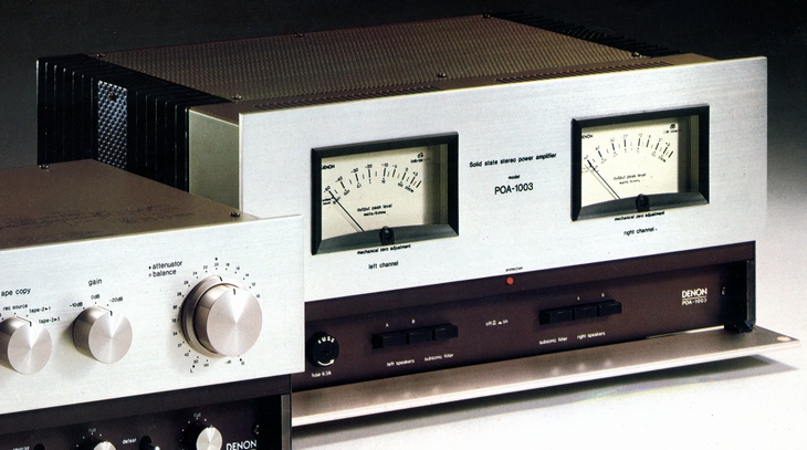
DENON POA-1003
¥ 145,000 (around 1977)
Commentary
Stereo power amplifier using DC amplifier system.
All stages of the ICL are directly connected OCL circuits. The first stage consists of a cascode-connected differential amplifier, the pre-drive stage consists of a differential-amplifier with emitter-follower input and naked gain increasing circuit, and the last stage consists of a Darlington-connected pure complimentary service push-pull.
A bipolar power transistor with good switching characteristics of Pc = 100W class is adopted for the output stage to obtain a sufficient output.
The power supply is constructed by 2 monaural construction using 2 power transformer system with independent left and right channels.
The final stage power supply circuit contains a strong transformer for each of the left and right channels and a large-capacity power supply smoothing capacitor of 44,000 μ F (88,000 μ F in total for the left and right channels) to provide sufficient margin for large amplitude input and to prevent crosstalk between channels.
A relatively large ripple current and a return current from the speaker flow through the return conductor from the 44,000 μ F smoothing capacitor to the power transformer. Therefore, even a small electrical resistance causes a noise voltage. Moreover, the potential of this part is grounded. It is connected to the first stage or control amplifier of the left and right channels that handle a small signal voltage. This deteriorates S/N and causes crosstalk.
In the POA-1003, this part is equipped with a Dual Bussler In (Dual Busline) with symmetrical left and right channels using a copper plate of 1 mm thickness to eliminate harmful effects.
Various measures are taken to suppress DC drift, which is a problem in DC amplifiers.
In the first stage differential circuit, TR1/2 is thermally coupled, and at the same time, the drain-source voltage is fixed by cascode connection (TR3/4) to reduce the gate current. In addition, to minimize the drift of the constant current circuit, a pattern layout method is adopted in which TR5 and the diode of its base circuit are thermally coupled.
In the pre-driver stage, the bipolar transistor TR8/9 of differential amplification is thermally coupled, and a high-precision resistor is used to minimize the effect on the first stage.
As a result of these considerations, the drift temperature coefficient is kept as low as 1.6 mV / ℃ and stable output is achieved.
The power stage, pre-drive stage and final stage transistors are supplied with independent power supplies. In particular, the first stage is equipped with a stabilized power supply circuit with low internal impedance. This ensures that even slight voltage fluctuations in the final stage do not affect the first stage and prevents dynamic crosstalk.
As a typical use of DC amplifier, the subsonic filter is designed to automatically turn on with a high-performance reed relay in case an abnormal DC voltage is applied to the input.
In the POA 1003, the output impedance is reduced to 1/4 of the conventional one by parallel use of relay and switch contacts and direct soldering of wiring.
Equipped with a logarithmic compression type peak meter.
Two types of peak levels, dB and WATT, can be read.
It is equipped with a protection circuit. When the power is turned on, the protection lamp turns on for approximately 10 seconds and no sound is emitted until the amplifier is in the normal state. This prevents the speaker from making a pop noise when the power is turned on.
When a DC voltage is generated at the output terminal, the relay that protects the speakers operates and the protection lamp lights up.
.JPG)
The input signal is applied to TR1, and the NFB from the output stage is applied to the gate of TR2.
This FET differential amplifier increases the in-phase signal rejection ratio by the constant current circuit of TR5, and cancels out in-phase noise and distortion generated by TR1/2 itself.
Emitter-follower TR6/7 receives the first stage output at an extremely high input impedance, and TR10 works to increase the bare gain of the differential amplification by TR8/9/11. The advantage of the current mirror type differential amplification is that the signal of TR8 is inverted by TR11, the output of TR8 and the output of TR9 are class A push-pull operation, so even order harmonic distortion is canceled out, and the output can be taken out at a low distortion rate from small amplitude to large amplitude operation..JPG)
Model Rating
| Type | Stereo power amplifier |
| Power Amplifier Unit Characteristics | |
| Dynamic output | 120W + 120W (8 Ω) |
| Rated output (both channel drive, sine wave output 20 Hz to 20 kHz) |
100W + 100W (4 Ω) 85W + 85W (8 Ω) |
| Total harmonic distortion factor | 0.005% (20 Hz, 1 kHz) 0.03%(20kHz) |
| Intermodulation distortion factor (60 hz : 7 khz = 4 : 1) | 0.02% (equivalent to rated output of 85W) |
| Output Bandwidth (IHF, both channel drives) | 3 Hz to 70 kHz |
| Transmission frequency characteristic | DC ~ 100 kHz + 0 -1dB |
| Input Sensitivity / Impedance | 1Vrms/50k Ω |
| Output impedance | 0.04 Ω |
| Damping factor | 200 (DC ~ 1 kHz) |
| Signal-to-noise ratio (IHF-A) | 119dB |
| Speaker terminal | A/B, 2 systems |
| Subsonic filter | 20 Hz, 6dB/oct. |
| Crosstalk | -95dB or less (20 Hz, 1 kHz) -90dB or less (20 kHz) |
| Level Meter Characteristics | |
| Indication range | -50 to + 3 dB (1 mW to 200W) |
| Indication error | -20 to + 3 dB ± 1.5 dB (0 dB = 100W/8 Ω) |
| Frequency characteristic | 10 Hz to 100 kHz |
| Response time | 100 msec (mechanical enemy response) |
| Recovery time | 0.5sec |
| Impedance | 50k Ω or more |
| <General> | |
| Semiconductor used | 2SC1775x10 Pieces 2SA818x4 Pieces 2SC1628x4 pcs 2SC1000x16 Pieces 2SA493x5 Pieces 2SD478x2 Pieces 2SA839x2 Pieces 2SC1116x2 Pieces 2SA747x2 Pieces 2SC458x3 Pieces 2SC1708x1 pc 2SA817x1 pc 2SA673x1 pc 2SC1626x3 Pieces 2SA816x2 Pieces 2SK68x4 Pieces 2SK30x2 Pieces Diode x62 pcs |
| Power supply voltage | 100 VAC, 50Hz/60Hz |
| Power consumption | 245W (Electrical Appliance and Material Control Law) |
| External Dimensions (Including Knobs and Feet) | Width 410x Height 200x Depth 285 mm |
| Weight | Approx. 17 kg |
.JPG)
.JPG)
.jpg)