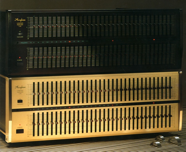
Accuphase G-18
¥ 330,000 (released in March 1985)
Commentary
A graphic equalizer designed for sound quality that was developed to correct transmission characteristics.
The G-18 is composed of 1/3-octave bands in order to make the transmission characteristics of the sound field as flat as possible, and the center frequency of each band is based on the ISO standard.
The variable frequency range is 16 Hz to 25 kHz to fully cover the audible range of 20 Hz to 20 kHz hz to 20 kHz.
Q, which determines the sharpness of the characteristics of each band, is the most ideal in the 1/3 octave system. Q = 4.3, which is -3dB at the point where an adjacent band intersects, can be selected. Also, when Q changes depending on the key level, the effect on the adjacent band becomes large. Therefore, the G-18 uses the constant Q system, in which Q does not change depending on the level control position of each band.
The bandpass filter, which controls the frequency by 1/3-octave band width, consists of two buffer amplifiers and 33 buffer amplifiers. In this circuit, when the output of the bandpass filter is at the center of the level control (0 dB position) of each band, each buffer amplifier acts as a flat amplifier with a gain of 1 and the frequency response becomes flat.
If you move the level control of the band-pass filter to a positive position, the signal is added to the input side of one buffer amplifier in phase, resulting in a convex characteristic. If you move the level control to a negative position, the signal is input to the other buffer amplifier, resulting in a concave characteristic. This signal is subtracted from the input side of the buffer amplifier, resulting in a negative characteristic.
Since the number of unit amplifiers is very large, general graphic equalizers use IC operational amplifiers to avoid circuit complexity, but the G-18 uses discrete amplifiers consisting of transistors and FETs for completeness.
The two buffer amplifiers have FET input, differential complimentary service and push-pull configuration, and the bandpass filter amplifier has differential complimentary service push-pull configuration to obtain excellent characteristics.
We also use carefully selected elements for C and R, which determine the band characteristics.
In addition to the normal phono jack input / output terminals, a balance input / output terminal using a cannon connector is mounted.
The balance input is switched between 600 Ω and high impedance 40k Ω, and the balance output is 50 Ω. All impedance balance inputs and outputs are supported.
The power supply section has a dedicated filter circuit with independent left and right windings, and the equalizer body has an independent left and right structure to prevent interference between channels.
In order to pursue only the function as a graphic equalizer, there is no input / output device such as a tape terminal.
The function consists only of an equalizer ON/OFF switch that passes the filter, and a simple signal path is provided.
It is recommended to insert it between the preamplifier and a power amplifier.
It comes with a smoked acrylic panel and the key position can be protected by inserting the pin attached to the acrylic side at the specified position on the panel surface.
The front panel is available in 2 colors, champagne gold and black.
The black color model name is G-18B.
There was a cabinet with natural wood Rosewood finish sold separately.
.jpg)
.jpg)
.jpg)
.jpg)
.jpg)
.jpg)
Model Rating
| Type | Graphic equalizer |
| Format | 1/3 octave 33 band type |
| Center frequency | 16, 20, 25, 31.5, 40, 50, 63, 80, 100, 125, 160, 200, 250, 315, 400, 500, 630, 800 Hz 1k, 1.25k, 1.6k, 2k, 2.5k, 3.15k, 4k, 5k, 6.3k, 8k, 10k, 12.5k, 16k, 20k, 25 kHz |
| Q (Peak Sharpness) | 4.3 Constant |
| Band level variable range | -12.0 dB to + 12.0 dB |
| Frequency characteristic (band level control : 0 dB) |
0.3 Hz ~ 160 kHz + 0 -3.0 dB 1.0 Hz ~ 40 kHz + 0 -0.2 dB |
| Gain | 0 dB (band level control : 0 dB) |
| Total harmonic distortion factor | 0.002% (EIA 16Hz-25kHz) |
| Rated input / output voltage | 2.0V |
| S/N(EIA) | 110dB |
| Input impedance | Unbalanced : 20k Ω Balanced : 40k Ω / 600 Ω switching type |
| Output impedance | Unbalanced : 10 Ω Balanced : 50 Ω |
| Load impedance | Unbalanced : 1k Ω or higher Balanced : 600 Ω or higher |
| Maximum input / output voltage | 8 vrms, + 20dBm/600 ohm (balanced output, band level control : 0 db) |
| Semiconductor used | Transistor : 706 units FET : 8 IC : 10 Diode : 129 units |
| Power supply voltage | AC100V/117V/220V/240V, 50Hz/60Hz |
| Power consumption | 55W |
| External Dimensions (Including Legs) | Width 445x Height 160x Depth 373 mm Width 466x Height 190x Depth 385 mm (with Wood Cabinet A-8) |
| Weight | 12.0kg |
| Attachment | Acrylic cover |
| Sold Separately | Wood Cabinet A-8 (¥ 16,000) |