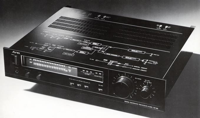
Aurex XD-80
¥ 280,000 (around 1981)
Commentary
This digital recording processor realizes high-quality PCM (Pulse Code Modulation) recording and playback by combining it with a home VTR.
In PCM, analog signals are digitally encoded and recorded on tape. Based on the EIAJ standard specifications, the original signal is sampled into 44,056 kHz pulses and the pulses are quantized. This realizes a dynamic range of more than 85 dB, characteristics of frequencies from 10 Hz to 20 kHz, a low distortion rate of less than 0.015%, 0 wow / flutter in practical use, and channel separation of more than 85 dB.
As a drop-out countermeasure, the XD-80 additionally records two correction codes (P code and Q code) and CRCC (error detection code) for every six data items during recording.
When a drop-out occurs during playback, errors are detected by the triple error detection method, which adds the H correlation data check method in addition to the syndrome check using CRCC check and EIAJ standard relational equation, and accurate correction is performed by the double correction function using two correction codes.
In addition, if uncorrectable data occurs, a correction process is performed using the average value of the previous and next correct data, and an operation called interleaving is performed to prevent data from being lost due to concentration.
Variable speed playback such as cue / review (approx. 20 x) / 2 x / 3 x / slow, which was impossible with the conventional PCM method, is possible. Still sound playback is also possible, making accurate head-tracking possible.
These functions are realized by a powerful anomaly detection circuit, a harmful signal rejection circuit, and a multiple PLL control system for generating the clock necessary for data and synchronizing signal separation.
You can connect two VTR decks and make digital copies.
It is possible to mix digital code reproduced by VTR with digital code of recorded input.
Equipped with a REC mute mechanism that is convenient for creating unrecorded space between songs when recording, or for cutting out unnecessary parts while copying. Since REC mute is done with digital signals, it is not affected by analog noise.
An emphasis circuit is built into the amplifier that handles analog signals during recording and playback. The emphasis circuit is applied to signals of 400 Hz or higher, and it performs high-frequency compensation of approximately 10 dB at 10 kHz.
Since the emphasis circuit can be turned ON / OFF with a switch, it can be used depending on the recording source.
Equipped with a level meter, the meter mode selector switch allows you to display the VTR tracking status during playback. This allows you to easily adjust the tracking to the best possible level by simply maximizing the meter display.
Equipped with an automatic mode selector (AMS) circuit. There are two VTR input jacks, one for playback and one for copying. When a video input signal is input to the duplicate input, mixing / duplicating (copying) is automatically enabled. When there is no signal in the duplicate input, normal mode is automatically enabled again.
You can switch between mixing and copying at the position of the master volume. When the volume is closed, the volume is copied. At other positions, the volume is set to mixing standby. An indicator shows the status of each of these.
During digital duplication (copy) or digital mixing operation, the digital attenuator of 6 dB can be turned ON / OFF for playback digital data, and the master volume can be used to fade in and out the recording source without changing the recording level.
The presence or absence of emphasis, copy prohibition, and operation status of parity (correction signal) Q are indicated by indicators.
These digital signals recorded on the tape are automatically detected during playback and the indicator lights.
Equipped with a headphone port with a dedicated volume.
Because the pulse played on a VTR is severely distorted compared to the recorded signal produced in a PCM processor, if the slice level that determines the 0 and 1 of the pulse is too high or too low, an accurate pulse cannot be reproduced.
To solve this problem, the XD-80 has an Automatic Data Slice Level Detector Control (ADSD) circuit that automatically adjusts the slice level to the best possible level for stable data extraction.
An ASSC (Analog Sync Slice Level Control) circuit is mounted to prevent timing deviation due to distortion of the sync (sync signal) caused by noise in the reproduced signal.
In this circuit, the slice level is automatically controlled to the optimum level and this timing gap is suppressed.
For analog circuits, we use high-performance elements that are used in high-end amplifiers based on technologies developed by Aurex.
The design emphasizes sound quality through the parallel use of u Λ -II type capacitors with low impedance, reduced contact between dissimilar metals, and improved vibration prevention, butyl-wound copper and styrene capacitors, butyl-wound copper and styrene capacitors, large-capacity GU capacitors (6.8 μ F/100V), and high-quality electrolytic capacitors.
Toshiba, Sony, and Sanyo have jointly developed three types of LSI for digital signal processing of PCM audio encoder and decoder whose format was standardized by EIAJ in March 1981. This LSI is also used in the XD-80.
This LSI is equipped with an ADSD circuit and an ASSC circuit to enable stable data extraction, and is equipped with a triple error detection method and error correction / correction method.
Since it supports both 14-bit and 16-bit systems, it can be used not only for 14-bit systems in the EIAJ standard format but also for 16-bit systems for business use.
With this newly developed LSI, it is possible to replace digital signal processing circuits that used to use hundreds of ICs with three different types of LSIs.
.JPG)
.JPG)
.JPG)
.JPG)
.JPG)
.JPG)
.JPG)
Model Rating
| Type | Digital recording processor |
| Signal Recording Format | |
| Signal recording format | PCM modulation system using video signal conforming to NTSC TV system |
| Code form | EIAJ standard format |
| Number of audio channels | 2 Channel |
| Standardized frequency | 44.056kHz |
| Number of quantization bits | 14-bit equivalent |
| Emphasis | T1 = 50 μ sec T2 = 15 μ sec ON-OFF enabled |
| Error correction system | Double correction word by P and Q |
| Reproduction Method | |
| Compound | 14-bit linear composite |
| Error correction | Double correction by P and Q Complete correction up to 2-word in 1 block (6 data words and 2 parity words / 1H) |
| Correction | Mean value correction |
| Emphasis | Automatic switching by emphasis control code |
| Re-recording Performance | |
| Frequency characteristic | 10 Hz to 20 kHz ± 0.5 dB |
| Harmonic distortion factor | Not more than 0.015% |
| Dynamic range | 85 dB or more |
| Wow and flutter | Below the measurement limit |
| Input / Output Terminal | |
| Line input | Terminal shapes : pin jacks Input impedance : 50k Ω unbalanced Adaptive signal source impedance : low impedance -14dB recording level : 90 mVrms 0 dB recording level : 550 mVrms Equivalent input noise voltage : 10 μ V or less Maximum allowable input level : Optional by Rec Level volume |
| Video input | Terminal shapes : pin jacks Input impedance : 75 Ω Unbalanced Adaptive signal source impedance : 75 Ω unbalanced Maximum allowable input level : 2.0Vp-p Specified input signal level : 1.0Vp-p |
| Line output | Terminal shapes : pin jacks Output impedance : 75 Ω Unbalanced Applicable load impedance : 10k Ω or more Unbalanced 0 dB playback level : up to 2 Vrms |
| Headphone out | Terminal Shape : φ 6.3 mm Stereo Headphone Jack Applicable load impedance : 8 Ω or more 0 dB playback level : up to 5 Vrms |
| Video Out | Terminal shapes : pin jacks Output impedance : 75 Ω Unbalanced Applicable Load Impedance : 75 Ω Unbalanced Specified output level : 1.0Vp-p (75 Ω load) |
| <Others> | |
| Input voltage | 100 VAC, 50Hz/60Hz |
| Power consumption | 30W |
| External dimensions | Width 450x Height 93x Depth 386 mm |
| Weight | 7.3kg |
| Attachment | US pin code |